– 30–
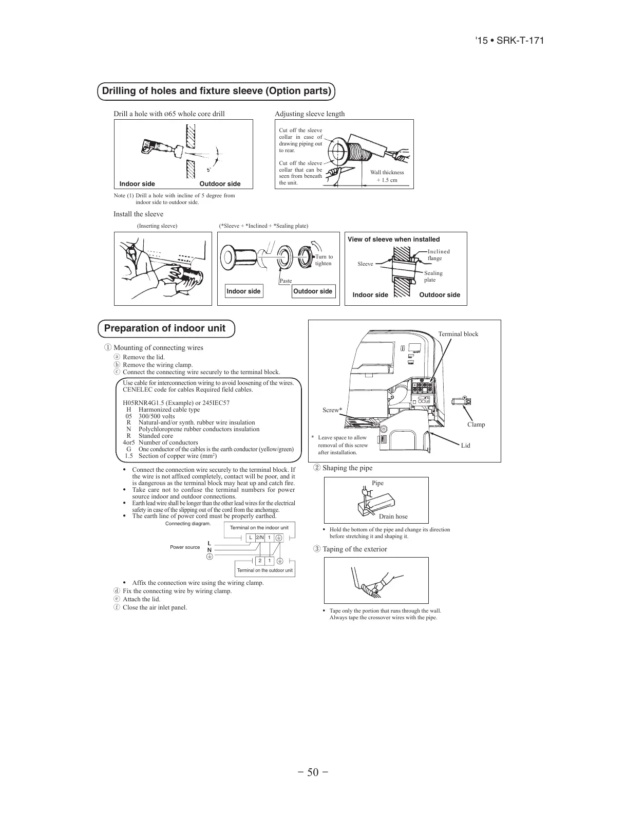
Drilling of holes and fixture sleeve (Option parts)
Drill a hole with Ø65 whole core drill
Install the sleeve
Adjusting sleeve length
Note (1) Drill a hole with incline of 5 degree from
indoor side to outdoor side.
Wall thickness
+ 1.5 cm
Cut off the sleeve
collar that can be
seen from beneath
the unit.
Cut off the sleeve
collar in case of
drawing piping out
to rear.
Indoor side
Indoor side
Indoor side
View of sleeve when installed
Outdoor side
Outdoor side
Outdoor side
(Inserting sleeve) (*Sleeve + *Inclined + *Sealing plate)
Paste
Sleeve
Turn to
tighten
Incline d
flange
Sealing
plate
Preparation of indoor unit
① Mounting of connecting wires
ⓐ Remove the lid.
ⓑRemove the wiring clamp.
ⓒConnect the connecting wire securely to the terminal block.
Use cable for interconnection wiring to avoid loosening of the wires.
CENELEC code for cables Required field cables.
75CEI542ro)elpmaxE(5.1G4RNR50H
H Harmonized cable type
05 300/500 volts
R Natural-and/or synth. rubber wire insulation
N Polychloroprene rubber conductors insulation
R Standed core
srotcudnocforebmuN5ro4
G
One conductor of the cables is the earth conductor (yellow/green)
1.5 Section of copper wire (mm
2
)
• Connect the connection wire securely to the terminal block. If
the wire is not affixed completely, contact will be poor, and it
is dangerous as the terminal block may heat up and catch fire.
• Take care not to confuse the terminal numbers for power
source indoor and outdoor connections.
•
Earth lead wire shall be longer than the other lead wires for the electrical
safety in case of the slipping out of the cord from the anchorage.
• The earth line of power cord must be properly earthed.
L
N
Connecting diagram.
Power source
Terminal on the indoor unit
L 2/N
2
N
L
1
1
Terminal on the outdoor unit
• Affix the connection wire using the wiring clamp.
ⓓFix the connecting wire by wiring clamp.
ⓔAttach the lid.
ⓕClose the air inlet panel.
② Shaping the pipe
③ Taping of the exterior
• Hold the bottom of the pipe and change its direction
before stretching it and shaping it.
• Tape only the portion that runs through the wall.
Always tape the crossover wires with the pipe.
* Leave space to allow
removal of this screw
after installation.
Pipe
Drain hose
Terminal block
Screw*
Clamp
Lid
RMA012A080_091-093_EN.indb 30 05/11/2014 11:50:41
 Loading...