-
101
-
2 2 2
2 2 2
2 2 2
22 22 22
2
Models SRC50ZSX-W, 60ZSX-W
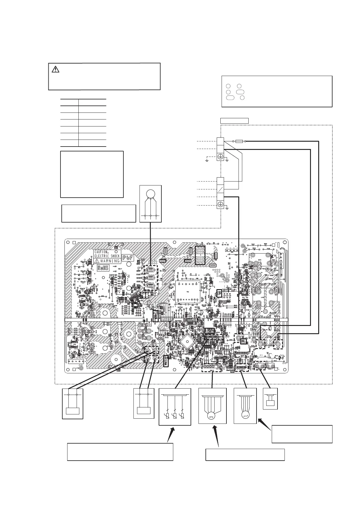
CAUTION
-
HIGH VOLTAGE
High voltage is produced in the control box. Don't touch
electrical parts in the control box for 5 minutes after the
unit is stopped.
◆Inspection of electronic
expansion valve
See page 102.
◆Inspection of resistance valve of sensor
Remove the connector and check the resistance valve.
See the section of sensor characteristics on page 92.
◆Power source and serial signal inspection
L to N : AC220/230/240V
1 to 2/N : AC220/230/240V
2/N to 3 : Normal if the voltage oscillates between
DC0 and approx. 20V
◆Inspection power transistor
Remove the fasten terminal and test
output voltage
◆Inspection of outdoor fan motor
See page 102.
◆Check point of outdoor unit
Color
Color symbol
RD
Mark
Yellow/GreenY/G
BlackBK
BlueBL
YellowYE
WhiteWH
Red
Display Voltage range
◆Voltage check in PCB
The normal range is as follows.
①DC280V DC230V - DC310V
②DC 20V DC 18V - DC 22V
③DC 13V DC 12V - DC 14V
④DC 15V DC 14V - DC 16V
⑤DC 5V DC 4V - DC 6V
⑥DC 2.5V DC 2.3V - DC 2.5V
M
T1
(WH)
(BK)
(RD)
V WU
M
CNTH
CNEEV
CNFAN
1 2 3 4 6
t゜
L1
(YE)
T2(YE)
2 2 2
TH1 TH2 TH3
EEV
FMo
t゜
t゜
MS
CM
3~
(BR)
(OR)
(RD)
(BL)
(WH)
T11
L2
(BL)
T12(BL)
(WH)
(BK)
(WH)
N
L
250V 20A
FUSE
2
1
N
3
(Y/G)
(Y/G)
(RD)
(RD)
20S
TB1
TB2
TERMINAL
BLOCK
TERMINAL
BLOCK
(WH)
(BK)
Power source
1 Phase
AC200-240V 50Hz
Indoor
unit
Outdoor unit
①
②
④
⑤
⑥
R.IN
(BK)
S.IN
C-2
③
(BK)
CN20S
 Loading...