-
27
-
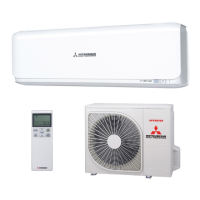
(Indoor Unit)
Model SRK20ZSX-W, -WB, -WT
Noise
Level
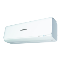
Cooling 53 dB(A)
Heating 55 dB(A)
×
......
Cooling,
Heating
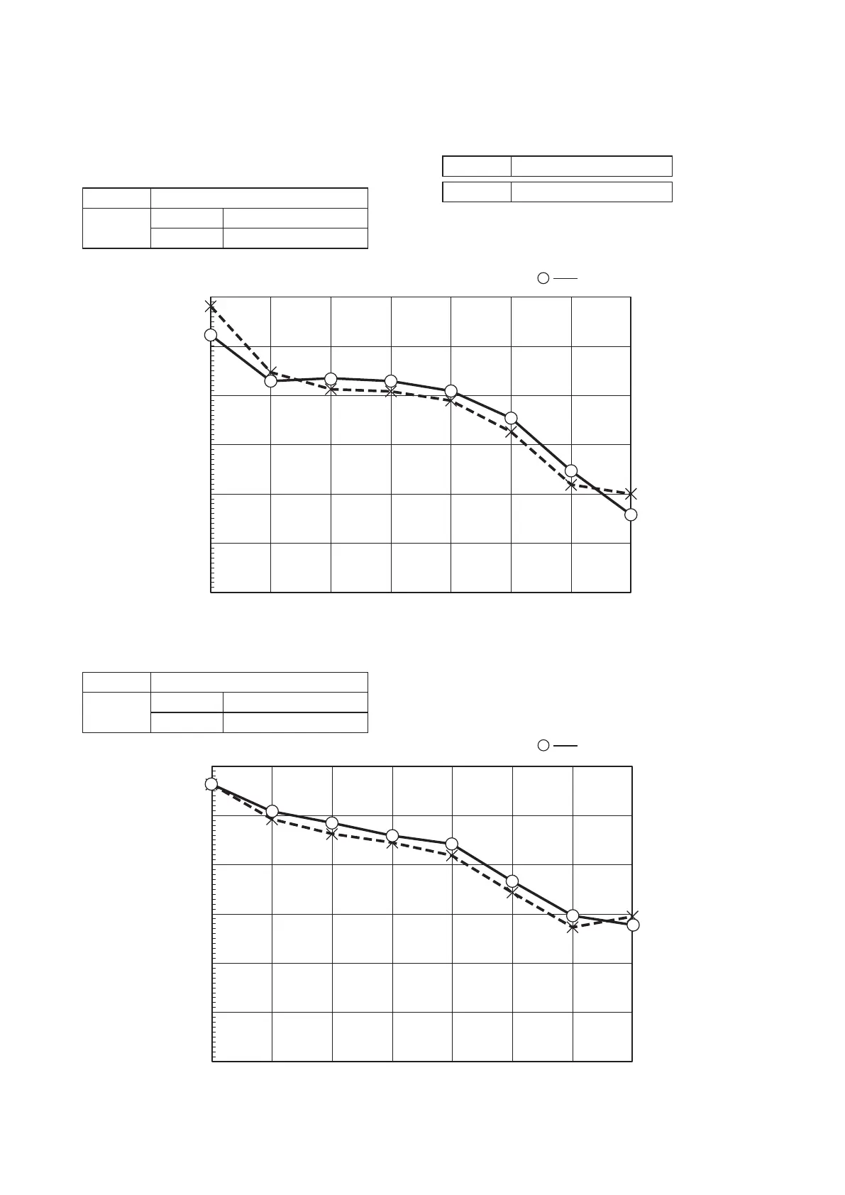
(Outdoor Unit)
Model SRC20ZSX-W
Noise
Level
Cooling 56 dB(A)
Heating 58 dB(A)
×
......
Cooling,
Heating
Condition ISO5151 T1/H1
MODE Rated capacity value (Hi)
4. NOISE LEVEL
(1) Sound power level
Model SRK20ZSX-W, -WB, -WT
30.0
20.0
10.0
40.0
50.0
60.0
70.0
Sound power level (dB)
63 125 250 500 1000 2000 4000 8000
Mid octave band frequency (Hz)
30.0
20.0
10.0
40.0
50.0
60.0
70.0
Sound power level (dB)
63 125 250 500 1000 2000 4000 8000
Mid octave band frequency (Hz)
TH3 Discharge pipe temp. sensor
TH2 Outdoor air temp. sensor
TH1 Heat exchanger sensor
L1,2 Reactor
FMo Fan motor
EEV Electric expansion valve(coil)
CM Compressor motor
CNTH
CNFAN
CNEEV
CN20S Connector
20S Solenoid coil for 4-way valve
Item Description
BK Black
Mark Color
BL Blue
RD Red
WH White
YE Yellow
YG
Model name
Power cable, indoor-outdoor connecting wires
MAX running current Power cable
wire size x number*(A)
Power cable length
(m)
Connecting cable
wire size x number*
SRC50ZSX-W
2.0mm x 3 13 1.5mm x 4
SRC60ZSX-W
15
2
2
Switchgear or Circuit breaker capacity should be chosen according to national or regional electricity
The power cable specifications are based on the assumption that a metal or plastic conduit is used
with no more than three cables contained in a conduit and a voltage drop is 2%. For an installation
falling outside of these conditions, please follow the national or regional electricity regulations.
The wire numbers include Earth wire(Yellow/Green)
*
regulations.
[ ]
2
N
M
(BK)
(WH)
(RD)
V
W
U
PCB ASSY PCB1
M
MS
TRANSISTOR
POWER
POWER
T 1A L 250V
CM
FMo
W
V
UP
N
CNTH CNEEV
CNFAN
3~
+
S.IN
R.IN
G1
N
L
250V 20A
F4
2
N
(YG)
C-2
(RD)
t゜
CN20S
(BK)
(WH)
(WH)
(WH)
F 3.15A L 250V
F1
(BK)
1
3
(BK)
(WH)
(YG)
(YG)
(RD)
G2
20S
(YG)
(BK)
~
~
+
-
SWITCHING
CIRCUIT
250V 20A
F8
++
CIRCUIT
PAM
CIRCUIT
PAM
(YE)
(BL)
T1
T11
T2
T12
(YE)
(BL)
+
F3
~
~
-
L1
L2
EEV
TH1 TH2 TH3
BLOCK
TERMINAL
2
2
2
3
TO INDOOR UNIT
4
Yellow/Green
BLOCK
TERMINAL
TB2
TB1
t゜
t゜
STACK1
DIODE
STACK2
DIODE
POWER CABLE
SIGNAL WIRE
EARTH WIRE
1
3
Power source
1 Phase
220-240V 50Hz
220V 60Hz
Color marks
Meaning of marks
 Loading...