-
55
-
6. FORMING PIPING AND DRAIN HOSE
1. Forming piping
Piping is possible in the right, rear, downward, left, left rear or left downward direction.
NOTE
the panels when connecting pipes.
Cut out the panel smoothly along the
line in case of side or bottom piping.
Left hand side piping Right hand side piping
Piping in the left direction
Piping in the left rear direction
Piping in the right rear direction
Piping in the right direction
Forming of pipings
• Hold the bottom of the
before stretching it
and shaping it.
Taping of the exterior
• Tape only the portion that
goes through the wall.
• Always tape the wiring
with the piping.
Pipings
2. Drain change procedures
(1) Remove the screw and drain hose.
(2) Remove the drain cap by hand or pliers.
(3) Insert the drain cap which was removed at procedure (2) securely using a hexagonal wrench etc.
(4) Install the drain hose and screw securely.
Screw
Drain cap
CAUTION
Incorrect installation of drain hose and cap can cause water leakage.
7. DRAINAGE WORK
• Arrange the drain hose in a downward angle.
• Avoid the following drain piping.
Wavy
The drain hose
tip is in water.
The gap to the ground
is 5 cm or less.
The drain hose tip
is in the gutter.
Odor from
the gutter
• Pour water to the drain pan located under the heat exchanger, and ensure that the water is discharged outdoor.
• When extended drain hose is present inside the room, insulate it securely with heat insulator available in the market.
Since this air-conditioner is designed to collect dew drops on the rear surface to the
drain pan, do not install the connecting wire above the gutter.
CAUTION
Incorrect drainage work can cause water leakage.
8. INSTALLING INDOOR UNIT
Installing the indoor unit to installation board Removing the indoor unit from installation board
(1) Remove the bottom panel. (Refer to 5.2)
(2) Pull the indoor unit base latch downward. (both right and left
hand sides). (The indoor unit base latch can be removed from the
installation board.)
(3) Push up the indoor unit upward so that it can be removed from
installation board.
Bottom panel
Wall
Installation board
Indoor unit base latch
(2 locations)
(1) Pass the pipe through the hole
in the wall, and hook the upper
part of the indoor unit to the
installation board.
(2)
Gently push the lower part to
fix the indoor unit base lower
latch to installation board.
Installation board
Wall
Installation board
Indoor unit base latch
(2 locations)
Latch (7 locations)
(3) Install the latches of the bottom panel
(7 locations).
Secure the bottom panel with the 3 screws
(in the cap).
9. CONNECTING PIPING WORK
1. Preparation of connecting pipe
1.1. Selecting connecting pipe
Select connecting pipe according to the following table.
Model SRK20/25/35 Model SRK50/60
Gas pipe ø9.52 ø12.7
Liquid pipe ø6.35 ø6.35
• Pipe wall thickness must be greater than or equal to 0.8 mm.
• Pipe material must be O-type (Phosphorus deoxidized seamless copper pipe ICS 23.040.15, ICS
77.150.30).
1.2. Cutting connecting pipe
(1) Cut the connecting pipe to the required length with pipe cutter.
(2)
Hold the pipe downward and remove the burrs. Make sure that no foreign material enters the pipe.
(3) Cover the connecting pipe ends with the tape.
2. Piping work
2.1. Flaring pipe
(1)
(2)
Flare dimensions for R32 are different from those for conventional refrigerant.
-
-
ment gauge.
Copper pipe
outer diameter
A
0
–0.4
B
Copper pipe
outer diameter
Rigid (clutch) type
R32 or R410A Conventional
ø6.35 9.1 ø6.35
0-0.5 1.0-1.5ø9.52 13.2 ø9.52
ø12.7 16.6 ø12.7
2.2 Connecting pipes
(1) Connect pipes on both liquid and gas sides.
Gas side
Service valve size (mm) Tightening torque (N·m)
ø6.35 (1/4") 14-18
ø9.52 (3/8") 34-42
ø12.7 (1/2") 49-61
CAUTION
•
can cause refrigerant leakage.
•
leakage.
3. Heating and condensation prevention
(1) Dress the connecting pipes (both liquid and gas pipes) with insulation to prevent it from heating and
dew condensation.
Use the heat insulating material which can withstand 120°C or higher temperature. Make sure that insu-
lation is wrapped tightly around the pipes and no gap is left between them.
(2) Wrap the refrigerant pipings of indoor unit with indoor unit heat insulation using tape.
(3) -
sulation pad (standard accessory provided with indoor unit).
(4) Wrap the connecting pipes, connecting cable and drain hose with the tape.
(2) (3) (4)
NOTE
Locations where relative humidity exceeds 70%, both liquid and gas pipes need to be dressed with 20mm
or
thicker heat insulation materials.
CAUTION
• Improper insulation can cause condensate(water) formation during cooling operation.
Condensate can leak or drip causing damage to household property.
• Poor heat insulating capacity can cause pipe outer surface to reach high temperature during heating
operation. It can cause cable deterioration and personal injury.
4. Finishing work
Pipe
assembly
(h)Screw
(1) Make sure that the exterior portion of connecting pipes, connecting cable and
drain hose is wrapped properly with tape. Shape the connecting pipes to match
with the contours of the pipe assembly route.
(2) Fix the pipe assembly with the wall using clamps and screws. Pipe assembly
should be anchored every 1.5m or less to isolate the vibration.
(3) Install the service cover securely. Water may enter the unit if service cover is
not installed properly, resulting in unit malfunction and failure.
WARNING
(only for R32)
•
must/shall be installed outdoors.
•
allowed indoors.
CAUTION
Make sure that the connecting pipes do not touch the components within the unit. If pipes touch the
internal components, it may generate abnormal sounds and/or vibrations.
10. HOW TO OPEN, CLOSE, REMOVE AND INSTALL
THE AIR INLET PANEL
13.
INSTALLING TWO AIR-CONDITIONERS IN THE SAME ROOM
1. Open
Pull the air inlet panel at both ends of lower part
and release latches, then pull up the panel until
you feel resistance.
(The panel stops at approx. 60° open position)
2. Close
Hold the panel at both ends of lower part, lower
it downward slowly, then push it slightly until the
latch works.
3. Removing
Open the panel by 80° (as shown in the right
illustration) and then pull it forward.
4. Installing
Insert the panel arm into the slot on the front
panel from the position shown in right illustration,
hold the panel at both ends of lower part, lower
it downward slowly, then push it slightly until the
latch works.
NOTE
• When carrying out maintenance, handle the air
inlet panel with care.
Approx. 80°
m
In case two air-conditioners are installed in the same room, apply this setting so that one unit can be
operated with only one wireless remote control.
Setting one wireless remote control
(1) Slide and take out the cover and batteries.
(2) Cut the switching line next to the battery with
wire cutters.
(3) Set the batteries and cover again.
Setting one indoor unit
(1) Turn off the power source and turn it on after 1
minute.
(2) Send the signal by pressing the ACL switch on
the wireless remote control that was set according
to the procedure described on the above side.
(3) Check that the reception buzzer sound “Peep”
is emitted from the indoor unit. Since the signal
is sent about 6 seconds after the ACL switch is
pressed, point the wireless remote control to the
indoor unit for a while.
NOTE
If no reception buzzer is emitted, restart the setting
from the beginning.
TIME SETUP ACL
Reception
Peep
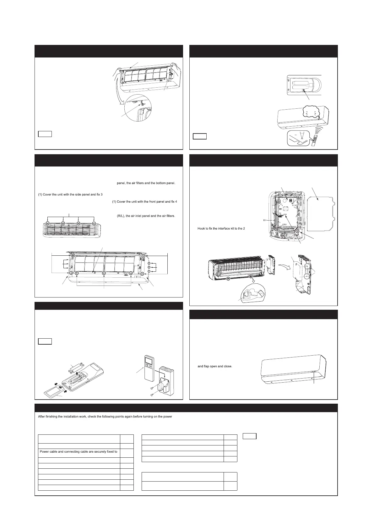
11. HOW TO REMOVE AND INSTALL THE SIDE AND
FRONT PANEL
14. TERMINAL CONNECTION FOR AN INTERFACE
1. Side panel (R/L)
1.1. Removing
(1) Remove the 2 screws.
(2) Remove the 3 latches and then side panel
can be removed.
1.2. Installing
latches.
(2) Secure the side panel with the 2 screws.
Latch
2. Front panel
2.1. Removing
(1) Remove the side panel (R/L), the air inlet
(2) Remove the 3 screws.
(3) Remove the 4 upper latches and then front
panel can be removed.
2.2. Installing
upper latches.
(2) Secure the front panel with the 3 screws.
(3) Install the bottom panel, the side panel
To install wired remote control, superlink etc., interface kit is needed.
(1)
Remove the air inlet panel, bottom panel
and side panel (R).
(2) Remove the control cover. (Remove the
screw.)
(3) There is a terminal (respectively marked
with CNS) for the indoor control board.
While connecting an interface, connect
to the respective terminal securely with
the connection harness supplied with
an option “Interface kit SC-BIKN-E and
SC-BIKN2-E” and fasten
the connection harness onto the indoor
control box with the clamp and screw
supplied with the kit.
(4)
latches on side panel (L).
For more details, refer to the user’s
manual of “Interface kit SC-BIKN-E and
SC-BIKN2-E”.
Indoor unit PCB
Control cover
Fixing point of
the clamp
Screw (Front panel)
Screw
Side panel (R
Latches
Side panel (R)
Side panel (L)
Latches
Side panel (L)
Pass the interface kit
12. INSTALLING WIRELESS REMOTE CONTROL
Mount the batteries
(1) Slide and take out the cover of backside.
(2) Mount the batteries [R03 (AAA, Micro),
×2 pieces] in the body properly.
(Fit he poles with the indication marks + & −)
(3) Set the cover again.
NOTE
• Do not use new and old batteries together.
• In case the unit is not operated for a long time,
take out the batteries
Installing remote control holder
(1) Select the place where the unit can receive
signals.
(2) Fix the holder to pillar or wall with wood
screws.
15. PUMP DOWN WORK
For the environmental protection, be sure to pump down when relocating or disposing of the unit.
Pump down is the method of recovering refrigerant from the indoor unit to the outdoor unit before the
connecting pipes are removed from the unit. When pump down is carried out, forced cooling opera-
tion is needed.
Forced cooling operation
(1) Turn off the power source and turn it on
again after 1 minute. The air inlet panel
(2) After the air inlet panel closes, press the
ON/OFF button continuously for at least 5
seconds. Then operation will start.
For the detail of pump down, refer to the
installation manual of outdoor unit.
Cover
16. INSTALLATION CHECK AND TEST RUN
. Conduct a test run and ensure that the unit operates properly.
At the same time, explain to the customer how to use the unit and how to take care of the unit following the user’s manual.
Before test run
Before test run, check following points.
Power source voltage complies with the rated voltage of
air-conditioner.
Earth leakage breaker and circuit breaker are installed.
the terminal block.
Both liquid and gas service valves are fully open.
No gas leaks from the joints of the service valves.
Indoor and outdoor side pipe joints have been insulated.
Hole on the wall is completely sealed with putty.
Drain hose and cap are installed properly.
Screw of the terminal cover is tightened securely.
Test run
Check following points during test run.
Indoor unit receives signal of wireless remote control.
Air-conditioning operation is normal.
There is no abnormal noise.
Water drains out smoothly.
Display of wireless remote control is normal.
After test run
Explain the operating and maintenance methods to the
user according to the user’s manual.
Keep this installation manual together with user’s
manual.
NOTE
During restart or change in operation mode, the unit will not start
operating for approximately 3 minutes. This is to protect the unit
and it is not malfunction.
Wood screws
ø3.5 X 16
Wireless remote control
Gas pipe
Insulation
Tape
Insulation pad
Position it so that the slit area faces upward.
Wall
Seal hole with putty
Flared joint outside
for indoor unit
Indoor
unit
Wall hole cover
Left
RLF012A202B_cc.indd 2 H29/09/21 20:19
 Loading...