-
59
-
4. CONNECTING PIPING WORK
1. Restrictions on unit installation
Abide by the following restrictions on unit installation.
Improper installation can cause compressor failure or performance degradation.
Dimensional restrictions
Model SRC20/25/35
Model SRC40/50/60
Connecting pipe length(L) 25m or less 30m or less
Elevation difference between
indoor and outdoor units(H)*
15m or less 20m or less
* Outdoor unit installation position can be higher as well as lower than the indoor unit installation position.
2. Preparation of connecting pipe
2.1. Selecting connecting pipe
Select connecting pipe according to the following table.
Model SRC20/25/35
Model SRC40/50/60
Gas pipe ø9.52 ø12.7
Liquid pipe ø6.35 ø6.35
• Pipe wall thickness must be greater than or equal to 0.8 mm.
• Pipe material must be O-type (Phosphorus deoxidized seamless copper pipe ICS 23.040.15, ICS
77.150.30).
NOTE
If it is required to reuse the existing connecting pipe system, refer to 5. UTILIZATION OF EXISTING
PIPE.
2.2. Cutting connecting pipe
(1) Cut the connecting pipe to the required length with pipe cutter.
(2) Hold the pipe downward and remove the burrs. Make sure that no foreign material enters the pipe.
(3) Cover the connecting pipe ends with the tape.
3. Piping work
Check that both liquid and gas service valves are fully closed.
Carry out the piping work with service valves fully closed.
Liquid service valve
Gas service valve
3.1. Flaring pipe
(1) Take out are nuts from the service valves of outdoor unit and engage them onto connecting pipes.
(2) Flare the pipes according to table and gure shown below.
Flare dimensions for R32 are different from those for conventional refrigerant.
Although it is recommended to use the aring tools designed speci cally for R32 or R410A, conventional
aring tools can also be used by adjusting the measurement of protrusion B with a are adjustment gauge.
Copper pipe
outer diameter
A
0
–0.4
Copper pipe
outer diameter
Rigid (clutch) type
R32 or
R410A
Conventional
ø6.35 9.1 ø6.35
0-0.5 1.0-1.5ø9.52 13.2 ø9.52
ø12.7 16.6 ø12.7
3.2. Connecting pipes
(1) Connect pipes on both liquid and gas sides.
(2) Tighten nuts to speci ed torque shown in the table below.
Service valve size (mm) Tightening torque (N·m)
ø6.35 (1/4") 14-18
ø9.52 (3/8") 34-42
ø12.7 (1/2") 49-61
Do not hold the valve cap area with a spanner
CAUTION
• Do not apply refrigerating machine oil to the ared surface. It can cause refrigerant leakage.
• Do not apply excess torque to the ared nuts. The ared nuts may crack resulting in refrigerant leakage.
4. Evacuation
(1) Connect vacuum pump to gauge manifold. Connect charge hose of gauge manifold to service port
of outdoor unit.
(2) Run the vacuum pump for at least one hour after the vacuum gauge shows -0.1MPa (–76cm Hg).
(3) Con rm that the vacuum gauge indicator does not rise even if the system is left for 15 minutes or more.
Vacuum gauge indicator will rise if the system has moisture left inside or has a leakage point.
Check the system for the leakage point. If leakage point is found, repair it and return to (1) again.
(4) Close the Handle Lo and stop the vacuum pump.
Keep this state for a few minutes to make sure that the compound pressure gauge pointer does not
swing back.
(5) Remove valve caps from liquid service valve and gas operation valve.
(6) Turn the liquid service valve's rod 90 degree counterclockwise with a hexagonal wrench key to open
valve.
Close it after 5 seconds, and check for gas leakage.
Using soapy water, check for gas leakage from indoor unit's are and outdoor unit's are and valve rods.
Wipe off all the water after completing the check.
(7) Disconnect charging hose from gas service valve's service port and fully open liquid and gas service
valves. (Do not attempt to turn valve rod beyond its stop.)
(8) Tighten service valve caps and service port cap to the speci ed torque shown in the table below.
Service valve size (mm)
Service valve cap tightening
torque (N·m)
Service port cap tightening
torque (N·m)
ø6.35 (1/4")
20-30
10-12ø9.52 (3/8")
ø12.7 (1/2") 25-35
Charge hose
Handle Lo
Valve cap
Liquid service valve
Gas service valve
Service port
Compound pressure gauge
Pressure gauge
Gauge manifold
Handle Hi
Vacuum pump
CAUTION
To prevent vacuum pump oil from entering into the refrigerant system, use a counter ow prevention adapter.
5. Additional refrigerant charge
Additional refrigerant charge is required only when connecting pipe length exceeds 15 m.
5.1 Calculating additional refrigerant charge
Additional refrigerant charge can be calculated using the formula given below.
Additional refrigerant charge (g) = { Connecting pipe length (m) – Factory charged length 15 (m) } x 20 (g/m)
NOTE
• If additional refrigerant charge calculation result is negative, there is no need to remove the refrigerant.
• If refrigerant recharge is required for the unit with connecting pipe length 15m or shorter, charge the
factory charged amount as shown in the table below.
• The maximum refrigerant charge amount is designed as shown in the table below.
Model SRC 20/25/35 Model SRC40/50/60
The factory refrigerant charge amount(kg) 1.20 1.30
The maximum refrigerant charge amount(kg) 1.40 1.50
5.2 Charging refrigerant
(1) Charge the R32 refrigerant in liquid phase from service port with both liquid and gas service valves
shut. Since R32 refrigerant must be charged in the liquid phase, make sure that refrigerant is dis-
charged from the cylinder in the liquid phase all the time.
(2) When it is dif cult to charge a required refrigerant amount, fully open both liquid and gas service
valves and charge refrigerant, while running the unit in the cooling mode. When refrigerant is
charged with the unit being run, complete the charge operation within 30 minutes.
(3) Write the additional refrigerant charge calculated from the connecting pipe length on the label at-
tached on the service cover.
CAUTION
•
Running the unit with an insuf cient quantity of refrigerant for a long time can cause unit malfunction.
•
Do not charge more than the maximum refrigerant amount. It can cause unit malfunction.
5. UTILIZATION OF EXISTING PIPE
(1) Check whether an existing pipe system is reusable or not by using the following ow chart.
Repair is impossible.
Air tightness is
impossible.
Repair is impossible.
Repair
Air tightness is OK.
Repair
Repair
NO
NO
NO
NO
NO
NO
NO
Are the outdoor and indoor units connected to the existing pipe system ?
Does the existing unit use any of the following refrigerant oils ?
Suniso, MS,Barell Freeze, HAB, Freol, ether oil, ester oil.
Do the existing pipe specifi cations (pipe length, pipe size and elevation difference between indoor and outdoor unit) conform to the restric-
tion of the unit.? (Go to 4.CONNECTING PIPING WORK and check 1.Restrictions on unit installation and 2.Preparation of connecting pipe.)
Is the existing pipe system free of gas leaks?
(Check whether refrigerant charge was required
frequently for the system before.)
Is the existing pipe system free of corrosion, fl aws and dents?
Are heat insulation materials of the existing pipe system
free of peel-off or deterioration?
(Heat insulation is necessary for both gas and liquid pipes.)
Is the existing piping system free of any loose pipe support ?
The existing pipe system is reusable.
The existing pipe system is not reusable.
Install the new pipe system.
Repair the damaged parts.
Check the pipe system for air tightness.
Repair the damaged parts.
Repair the loose pipe support.
NO
Is it possible to run the unit ?
YES
YES
YES
YES
YES
YES
YES
YES
NOTE
• Consult with our distributor in the area, if you need to recover refrigerant and charge it again.
(2) Clean the existing pipe system according to the procedure given below.
(a) Carry out forced cooling operation of existing unit for 30 minutes.
For ‘Forced cooling operation’ refer to the indoor unit installation manual.
(b) Stop the indoor fan and carry out forced cooling operation for 3 minutes (Liquid return).
(c) Close the liquid service valve of the outdoor unit and carry out pump down operation (Refer to 6.
PUMP DOWN).
(d) Blow with nitrogen gas. If discolored refrigeration oil or any foreign matter is discharged by the
blow, wash the pipe system or install a new pipe system.
(3) Remove the are nuts from the existing pipe system. Go back to 4.CONNECTING PIPING WORK
and proceed to step 2.2 Cutting connecting pipe.
CAUTION
• Do not use the old are nuts (of existing unit). Make sure that the are nuts supplied with the (new)
outdoor unit are used.
• If the ared / compression connection to the indoor unit is located inside the house / room then this
pipework can’t be reused.
* If the existing piping is speci ed as liquid pipe ø9.52 or gas pipe ø12.7, refer to the following. (SRC40,50
and 60 only)
<Table of pipe size restrictions>
Additional charge volume per meter of pipe 0.054kg/m
Pipe size
Liquid pipe ø9.52
Gas pipe ø12.7
Maximum one-way pipe length 10
Length covered without additional charge 5
Additional charge amount (kg) = {Main pipe length (m) - Length covered without additional
charge shown in the table (m)} X Additional charge amount per meter of pipe shown in the table (kg/m)
6. PUMP DOWN
(1) Connect charge hose of gauge manifold to service port of outdoor unit.
(2) Close the liquid service valve with hexagonal wrench key.
(3) Fully open the gas service valve with hexagonal wrench key.
(4) Carry out forced cooling operation (For forced cooling operation procedure, refer to indoor unit installation
manual).
(5) When the low pressure gauge becomes 0.01MPa, close the gas service valve and stop forced cooling
operation.
Service port
Gauge manifold
Charge hose
7. ELECTRICAL WIRING WORK
WARNING
• Make sure that all the electrical work is carried out in accordance with the national or regional electri-
cal standards.
• Make sure that the earth leakage breaker and circuit breaker of appropriate capacities are installed
(Refer to the table given below).
• Do not turn on the power until the electrical work is completed.
• Do not use a condensive capacitor for power factor improvement under any circumstances.
(It does not improve power factor. Moreover, it can cause an abnormal overheat accident).
Breaker speci cations
Model Phase Earth leakage breaker Circuit breaker
SRC20/25/35
Single phase
Leakage current: 30mA,
0.1sec or less
Over current: 16A
SRC40/50/60 Over current: 20A
Main fuse speci cation
Model Speci cation Parts No. Code on LABEL,WIRING
SRC20/25/35 250V 15A SSA564A136 F7
SRC40/50/60 250V 20A SSA564A136A F4
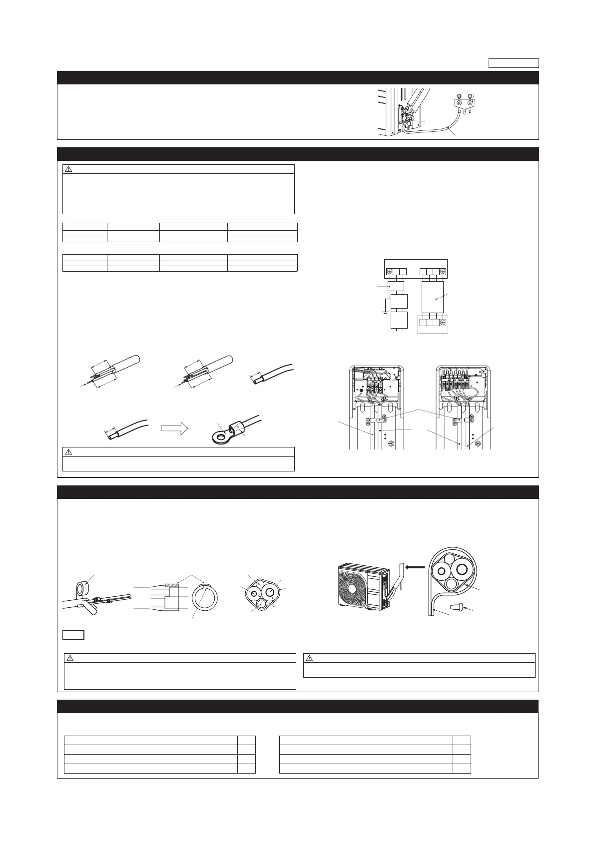
1.Preparing cable
(1) Selecting cable
Select the power source cable and connecting cable in accordance with the speci cations mentioned below.
(a) Power source cable
3 cores* 2.5mm
2
or more, conformed with 60245 IEC57
When selecting the power source cable length, make sure that voltage drop is less than 2%.
If the wire length gets longer, increase the wire diameter.
(b) Connecting cable
4 cores* 1.5mm
2
, conformed with 60245 IEC57
* 1 Earth wire is included (Yellow/Green).
(2) Arrange each wire length as shown below.
Make sure that each wire is stripped 10mm from the end.
<Power source cable> <Connecting cable> <Wire end>
e
40mm or more
40mm or more
e
(3) Attach round crimp-type terminal to each wire as shown in the below.
Select the size of round crimp-type terminal after considering the speci cations of terminal block and wire
diameter.
Round crimp-type terminal
Sleeve
CAUTION
Power source cable and connecting cable must conform to the speci cations mentioned in the manual.
Using cables with wrong speci cations may result in unit malfunction.
2.Connecting cable
(1) Remove the service cover.
(2) Connect the cables according to the instructions and gures given below.
(a) Connect the earth wire of power source cable.
An earth wire must be connected before connecting the other wires of power source cable.
Keep the earth wire longer than the remaining two wires of power source cable.
(b) Connect the remaining two wires (N and L) of power source cable.
(c) Connect the wires of connecting cable. Make sure that for each wire, outdoor and indoor side ter-
minal numbers match.
(3) Fasten the cables properly with cable clamps so that no external force may work on terminal connec-
tions.
Moreover, make sure that cables do not touch the piping, etc. When cables are connected, make sure
that all electrical components within the electrical component box are free of loose connector coupling
or terminal connection.
<Circuit diagram>
NL
12/N 3
12/N 3
Circuit
breaker
Earth
leakage
breaker
Earth
Power
Indoor unit
Outdoor unit
Connecting cable
Power
source
cable
<SRC20/25/35> <SRC40/50/60>
Power
source
cable
cable
e
Cable clamp
8. FINISHING WORK
1. Heating and condensation prevention
(1) Dress the connecting pipes (both liquid and gas pipes) with insulation to prevent it from heating
and dew condensation.
Use the heat insulating material which can withstand 120°C or higher temperature. Make sure that
insulation is wrapped tightly around the pipes and no gap is left between them.
(2) Wrap the refrigerant pipings of indoor unit with indoor unit heat insulation using tape.
(3) Cover the are-connected joints (indoor side) with the indoor unit heat insulation and wrap it with
an insulation pad (standard accessory provided with indoor unit).
(4) Wrap the connecting pipes, connecting cable and drain hose with the tape.
(2) (3) (4)
Insulation pad
Position it so that the slit area faces upward.
Connecting cable
Liquid pip
e
Insulation
Tape
NOTE
Locations where relative humidity exceeds 70%, both liquid and gas pipes need to be dressed with 20mm
or
thicker heat insulation materials.
2.Finishing work
(1) Make sure that the exterior portion of connecting pipes, connecting cable and drain hose is wrapped
properly with tape. Shape the connecting pipes to match with the contours of the pipe assembly route.
(2) Fix the pipe assembly with the wall using clamps and screws. Pipe assembly should be anchored ev-
ery 1.5m or less to isolate the vibration.
(3) Install the service cover securely. Water may enter the unit if service cover is not installed properly,
resulting in unit malfunction and failure.
Screw
CAUTION
• Improper insulation can cause condensate(water) formation during cooling operation.
Condensate can leak or drip causing damage to household property.
• Poor heat insulating capacity can cause pipe outer surface to reach high temperature during heating
operation. It can cause cable deterioration and personal injury.
CAUTION
Make sure that the connecting pipes do not touch the components within the unit. If pipes touch the
internal components, it may generate abnormal sounds and/or vibrations.
9. INSTALLATION TEST CHECK POINTS
After nishing the installation work, check the following points again before turning on the power.
Conduct test run (Refer to indoor unit installation manual) and ensure that the unit operates properly.
RWC012A063B
Power source voltage complies with the rated voltage of air-conditioner.
Earth leakage breaker and circuit breaker are installed.
Power cable and connecting cable are securely xed to the terminal block.
Both liquid and gas service valves are fully open.
No gas leaks from the joints of the service valves.
Indoor and outdoor side pipe joints have been insulated.
Drain hose (if installed) is xed properly.
Screw of the service cover is tightened properly.
 Loading...