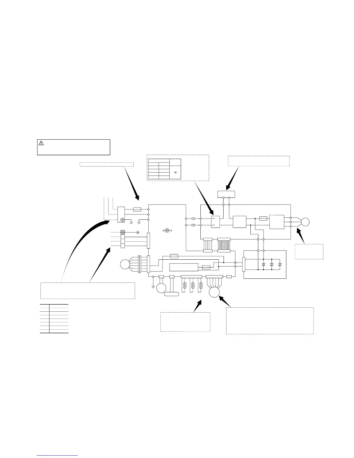
● Inspection of resistance value of
dischargepipe sensor.
Remove the connector and check the resis-
tance value. See the section of sensor char-
acteristics on page 116.
● Inspection of electronic expansion valve
To test if there is voltage.
(Voltage is only applied to the electronic expansion valve when the
valve angle is being changed.)
Red to white
Red to Orange
Brown to yellow
Brown to blue
If the expansion valve does not operate as shown above, it
is defective.
}
(When tester probes
are inverted, the
reading should be
approx. 10~20Ω.)
● Inspection of diode stack (DS1)
Tester probe
Normal
condition
,
+ (OR)
+ (OR)
~ (BL)
~ (GR)
.
~ (BL)
~ (GR)
– (BK)
– (BK)
● Inspection of inductor conductivity
Remove the connector and check for conduc-
tivity. It must be conductive.
● Inspect power
transistor.
Remove the fasten
terminal and test out-
put voltage.
Check fuse. There should be conductivity.
CAUTION – HIGH VOLTAGE
(ii) Outdoor unit inspection points
High voltage is produced in the control box. Don't touch
electrical parts in the control box for 5 minutes after the
unit is stopped.
SSRC22ZEV-S
¡Power source and serial signal inspection
L to N: AC220V
1 to 2: AC220V
2 to 3: Normal if the voltage oscillates between DC 0 and approx. 12V
Normal if there is approximately DC 5 V 10 seconds
after the power supply is turned on.
BK
Color symbol
BL
OR
Y/G
Black
Blue
Orange
Yellow/Green
WH White
RD Red
GR Green
Y Yellow
2/N
1
3
Y/GN
BK
WH
RD
TB
DC-P
DC-N
AF-L2 AF-L1
AC.L
AC.N
Q1
Power
transistor
250V
F
AC.N
AC.L
P
N
U
V
W
RD
WH
BK
GR GR
BL BL
L
N1 N2
P2
IC2
+
-
DS1
L
OR OR
P_1N_1
Switching
power circuit
BK
RD
RD
BK
+++
P_1N_1
1
2
20A
WH
Y/G
BK
N-1
G3
L-1
Power Source
1 Phase
220V 50Hz
Indoor unit
L
N
Y/G
G2
HEATER
250V 2A
F
4
6
F1
250V 2A
C1 C1
C1
F
250V 20A
PWB1
PWB2
PWB3
CNT
CNG CNH
CNG
CNH
CNG
CNDCNB
CNJ
CNO
CNI
CNC
FMo
CM
20S
EEV
Th4 Th5 Th6
RL
 Loading...