(BK)
(WH)
(RD)
V
W
U
PCB ASSY PCB1
M
MS
TRANSISTOR
POWER
POWER
T 1A L 250V
W
V
UP
N
CNTH CNEEV
CNFAN
3~
+
S.IN
R.IN
G1
250V 20A
F4
C-2
(RD)
CN20S
(WH)
(WH)
F 3.15A L 250V
F1
(BK)
(BK)
(WH)
(YG)
(YG)
(RD)
G2
20S
~
~
+
-
SWITCHING
CIRCUIT
250V 20A
F8
++
(YE)
(BL)
T1
T11
T2
T12
(YE)
(BL)
F3
~
~
+
-
FILTER
NOISE
L 1
N 2
3
(YG)
TB1
L1
L2
EEV
FMo
CM
TH3TH2TH1
2 2 22
(BK)
4
3
M
t゜
t゜
t゜
CIRCUIT
PAM
CIRCUIT
PAM
BLOCK
TERMINAL
STACK1
DIODE
STACK2
DIODE
Power source
1 Phase
220-240V 50Hz
220V 60Hz
(BK)
(WH)
(RD)
V
W
U
PCB ASSY PCB1
M
MS
TRANSISTOR
POWER
POWER
T 1A L 250V
W
V
UP
N
CNTH CNEEV
CNFAN
3~
+
S.IN
R.IN
G1
250V 20A
F4
C-2
(RD)
CN20S
(WH)
(WH)
F 3.15A L 250V
F1
(BK)
(BK)
(WH)
(YG)
(YG)
(RD)
G2
20S
~
~
+
-
SWITCHING
CIRCUIT
250V 20A
F8
++
(YE)
(BL)
T1
T11
T2
T12
(YE)
(BL)
F3
~
~
+
-
FILTER
NOISE
L 1
N 2
3
(YG)
TB1
L1
L2
EEV
FMo
CM
TH3TH2TH1
2 2 22
(BK)
4
3
M
t゜
t゜
t゜
CIRCUIT
PAM
CIRCUIT
PAM
BLOCK
TERMINAL
STACK1
DIODE
STACK2
DIODE
Power source
1 Phase
220-240V 50Hz
220V 60Hz
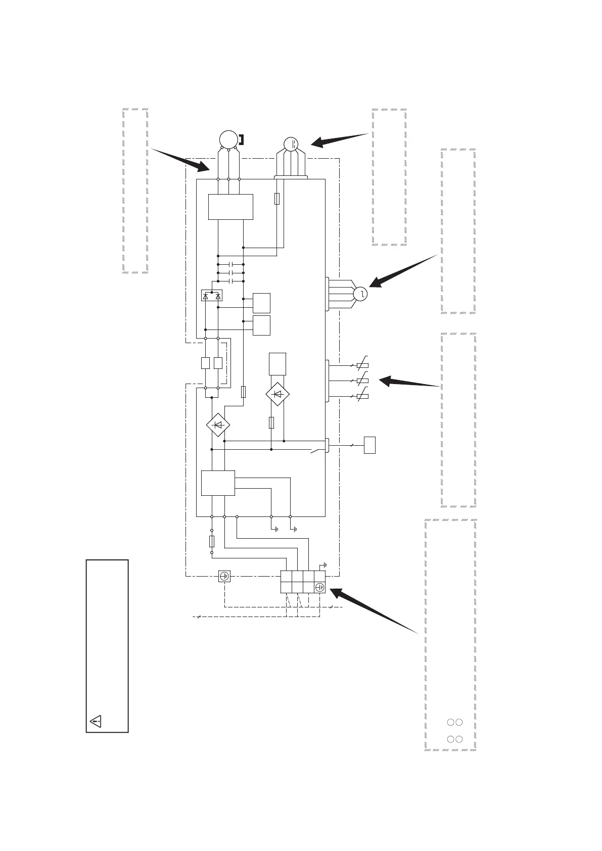
◆ Check point of outdoor unit
CAUTION
-
HIGH VOLTAGE
High voltage is produced in the control box. Don't touch
electrical parts in the control box for 5 minutes after the
unit is stopped.
◆Power source and serial signal inspection
1
to
2
:
AC 220/230/240V
2 to
3 : Normal if the voltage oscillates between DC 0 and approx. 20V
◆Inspection of resistance value of sensor
Remove the connector and check the resistance value.
See the section of sensor characteristics on page 27.
◆Inspection power transistor
Remove the fasten terminal and test output voltage.
◆Inspection of electronic expansion valve
See page 36.
◆Inspection of outdoor fan motor
See page 36.
 Loading...