'18 • SRK-SM-259
-
36
-
(a) Inspection of electronic expansion valve
Electronic expansion valve operates for approx. 10 seconds after the power on, in order to determine its aperture. Check
the operating sound and voltage during the period of time. (Voltage cannot be checked during operation in which only
the aperture change occurs.)
(i) If it is heard the sound of operating electronic expansion valve, it is almost normal.
(ii) If the operating sound is not heard, check the output voltage.
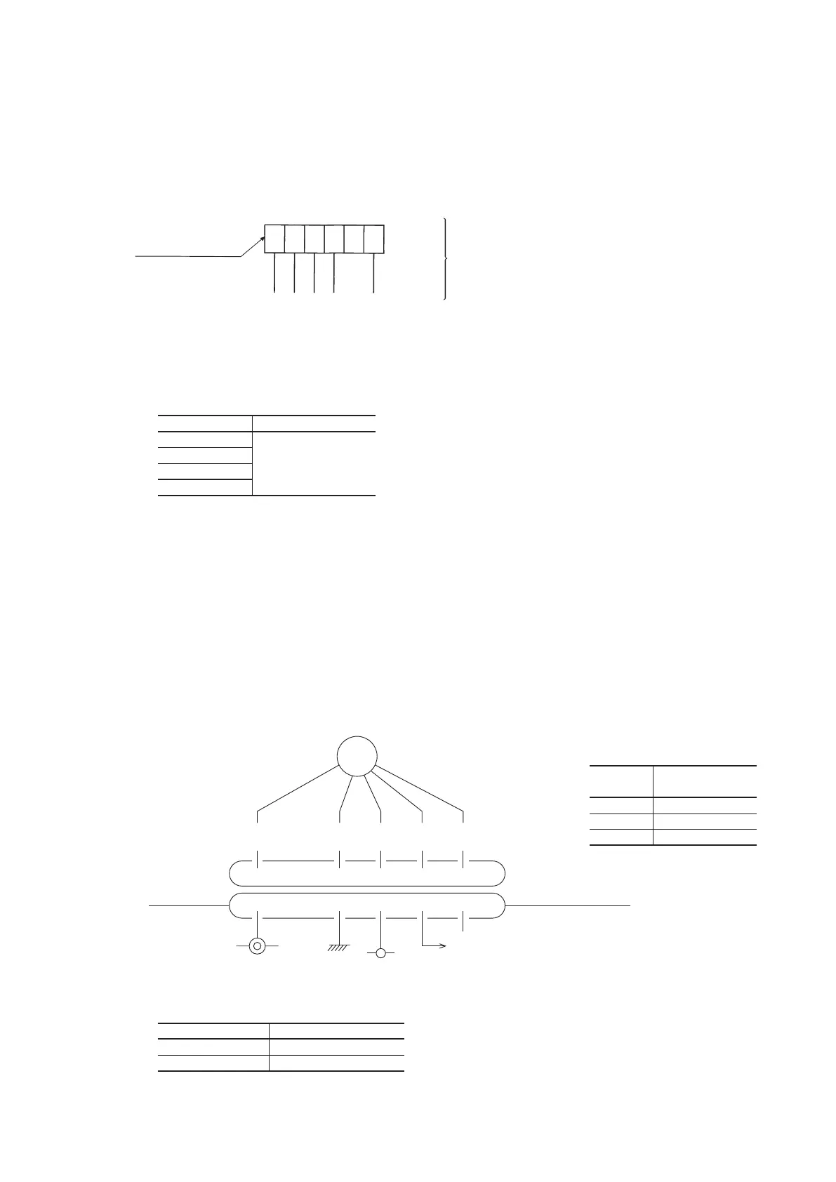
Expansion valve connector
(6P, black)
Approx. DC5 V is detected for 10 seconds after the power on.
6
White
Yellow
Blue
Red
54
3
2
1
1
-
3
1
-
4
1
-
5
1
-
6
(iii) If voltage is detected, the outdoor unit PCB is normal.
(iv) If the expansion valve does not operate (no operating sound) while voltage is detected, the expansion valve is
defective.
(b) Outdoor unit fan motor check procedure
• When the outdoor unit fan motor error is detected, diagnose which of the outdoor unit fan motor or outdoor unit PCB
is defective.
• Diagnose this only after conrming that the indoor unit is normal.
(i) Outdoor unit PCB output check
1) Turn off the power.
2) Disconnect the outdoor unit fan motor connector CNFAN.
3) When the indoor unit is operated by inserting the power source plug and pressing (ON) the backup switch for more
than 5 seconds, if the voltage of pin No.
②
in the following gure is output for 30 seconds at 20 seconds after
turning “ON” the backup switch, the outdoor unit PCB is normal but the fan motor is defective.
If the voltage is not detected, the outdoor unit PCB is defective but the fan motor is normal.
Note (1) The voltage is output 3 times repeatedly. If it is not detected, the indoor unit displays the error message.
(ii) Fan motor resistance check
Notes (1) Remove the fan motor and measure it without power connected to it.
Notes (2) If the measured value is below the value when the motor is normal, it means
that the fan motor is faulty.
Measuring point Resistance when normal
⑥
-
④
(Red
-
Black) 20 MΩ or higher
③
-
④
(White
-
Black) 20 kΩ or higher
Measuring
point
Voltage range when
normal
⑥
-
④
DC 308-336V
③
-
④
DC 15V
②
-
④
DC several V (4-7V)
DC15V
DC several (4-7V)
Outdoor unit PCB
GND
DC308-336V
CNFAN
Red
Black
White
Yellow
Blue
①②③④⑤⑥
①②③④⑤⑥
FM0
• Inspection of electronic expansion valve as a separate unit
Measure the resistance between terminals with an analog tester.
Measuring point Resistance when normal
1
–
6
46 ± 4Ω
(at 20ºC)
1
–
4
1
–
3
1
–
5
 Loading...