Color
RD
Mark
OrangeOR
Yellow/GreenY/G
BlackBK
YellowY
WhiteWH
Red
(BK)
C-2
G1
(RD)
(Y/G)
S.IN(WH)
R.IN
(BK)
(WH)
(RD)
PWB ASSY
250V 20A
F2
F3 250V 1A
F4
250V 10A
F1
250V 2A
CIRCUIT
PAM
SWITCHING POWER
CIRCUIT
N
P
W
V
U
TRANSISTOR
POWER
W
V
U
FILTER
NOISE
CN20S
CNTH
CNEEV
CNFAN
M
M
3
~
250V 15A
T1
T2
(OR)
(Y)
M
t
゜
20S
TH1 TH2 TH3
EEV
FMo
CM
t
゜
t
゜
t゜
L
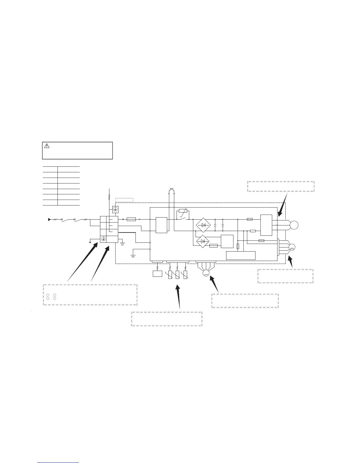
◆Inspection of resistance value of sensor
Remove the connector and check the resistance value.
See the section of sensor characteristics on page 51.
◆Inspection power transistor
Remove the fasten terminal and test output voltage
◆Inspection of electronic expansion valve
See page 59.
◆Inspection of outdoor fan motor
See page 59.
◆ Check point of outdoor unit
CAUTION
-
HIGH VOLTAGE
High voltage is produced in the control box. Don't touch
electrical parts in the control box for 5 minutes after the
unit is stopped.
Color symbol
Outdoor unit
◆Power source and serial signal inspection
1
to 2 : AC 220/230/240V
2 to 3 : Normal if the voltage oscillates between DC 0 and approx. 20V
AC220ー240V 50Hz
POWER
(Y/G)
L
N
1
3
2
TB
(11) Outdoor unit inspection points
Models SRK25ZMP-S, 35ZMP-S, 45ZMP-S
 Loading...