1
(Vig. II)
(rig.lo)
a. Adjust the bolts on the backside of Head "B" (Fig.9).
b. By loosening the head fastening bolt and by tightening the head adjusting
bolt, the head proceeds toward the operator.
c. By opposite manipulation-by tightening the head fastening bolt and by
loosening the head adjusting bolt, the head recedes.
d. Adjusting by the fastening bolt only, or by the adjusting bolt only,
may suffice depending on the amount of adjustment needed.
e. This adjustment can be made at the four corners. Sometimes, adjustment of
one corner only may suffice, but all of the four comers may need adjusting
depending on the actual situation.
f. Amount of adjustment can be determined by the following checks.
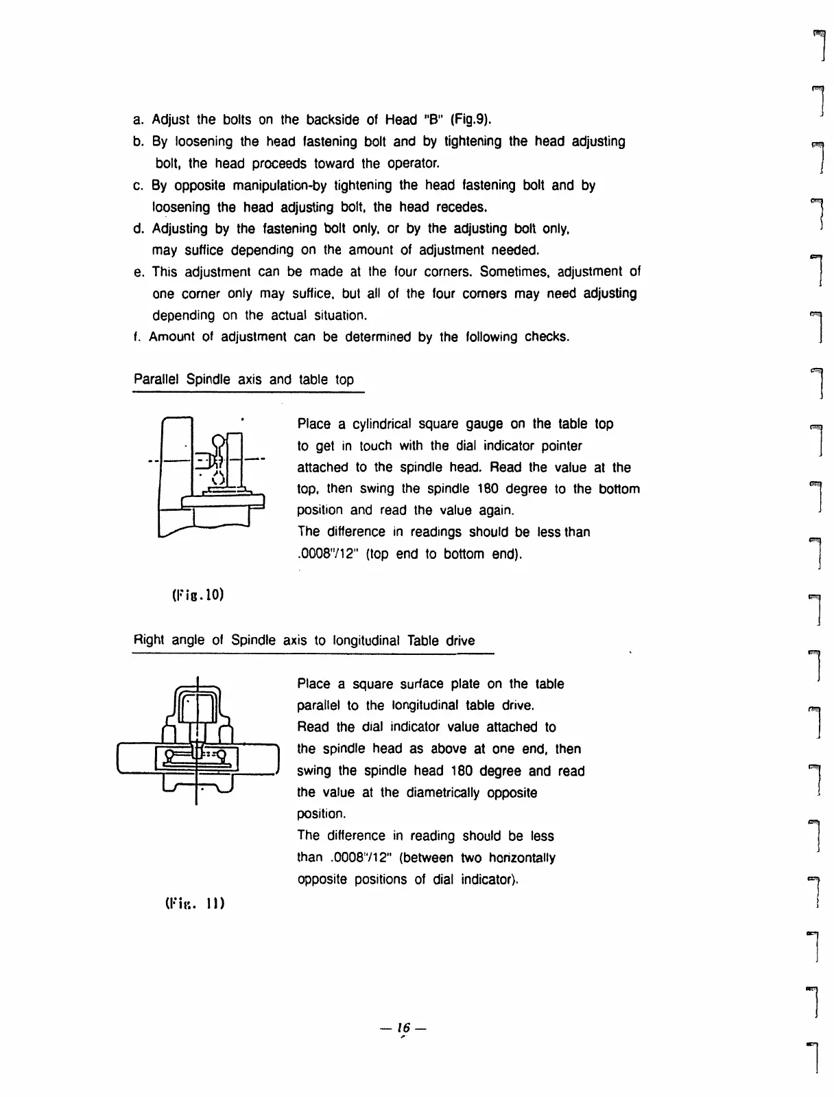
Parallel Spindle axis and table top
Place a cylindrical square gauge on the table top
to get in touch with the dial indicator pointer
attached to the spindle head. Read the value at the
top, then swing the spindle 180 degree to the bottom
position and read the value again.
The difference in readings should be less than
.0008712" (top end to bottom end).
Right angle of Spindle axis to longitudinal Table drive
Place a square surface plate on the table
parallel to the longitudinal table drive.
Read the dial indicator value attached to
the spindle head as above at one end, then
swing the spindle head 180 degree and read
the value at the diametrically opposite
position.
The difference in reading should be less
than .0008/12" (between two horizontally
opposite positions of dial indicator).
Cl
— 16 —
-
 Loading...