6. STRUCTURE, MECHANISM AND
ADJUSTING OF MACHINE' S MAIN PARTS
777?
773
171
Thorough knowledge of the structure, mechanism and adjusting of the machine's
main parts is very much desired for the operator to make the most of this
surface grinder, for optimal performance and preventive maintenance as well as
safety.
A. GRINDING HEAD (Common to MSG-25OM/25OMH and MSG-2OOM /2OOMHI)
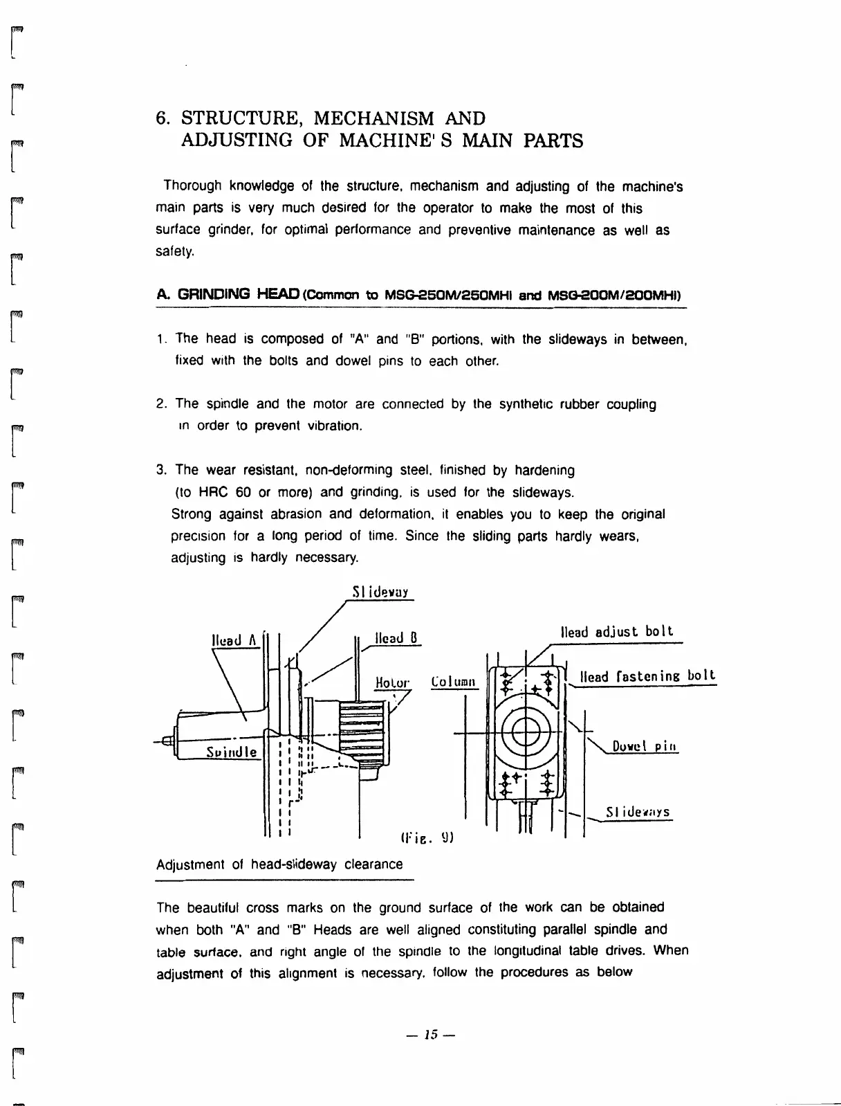
1, The head is composed of "A" and "B" portions, with the slideways in between,
fixed with the bolts and dowel pins to each other.
2. The spindle and the motor are connected by the synthetic rubber coupling
in order to prevent vibration.
3. The wear resistant, non-deforming steel, finished by hardening
(to HRC 60 or more) and grinding, is used for the slideways.
Strong against abrasion and deformation, it enables you to keep the original
precision for a long period of time. Since the sliding parts hardly wears,
adjusting is hardly necessary.
head A
Spindle
r-I
SI idevay
Head B
Motor Column
mvon,2=E32.,
(Fig. 9)
Adjustment of head-slideway clearance
Head adjust bolt
Head fastening bolt,
N Dowel pin
SI i ded;i y s
The beautiful cross marks on the ground surface of the work can be obtained
when both "A" and "B" Heads are well aligned constituting parallel spindle and
table sudace, and right angle ol the spindle to the longitudinal table drives. When
adjustment of this alignment is necessary, follow the procedures as below
— 15 —
 Loading...