3. The screw height may be adjusted similarly as per C. 3, above.
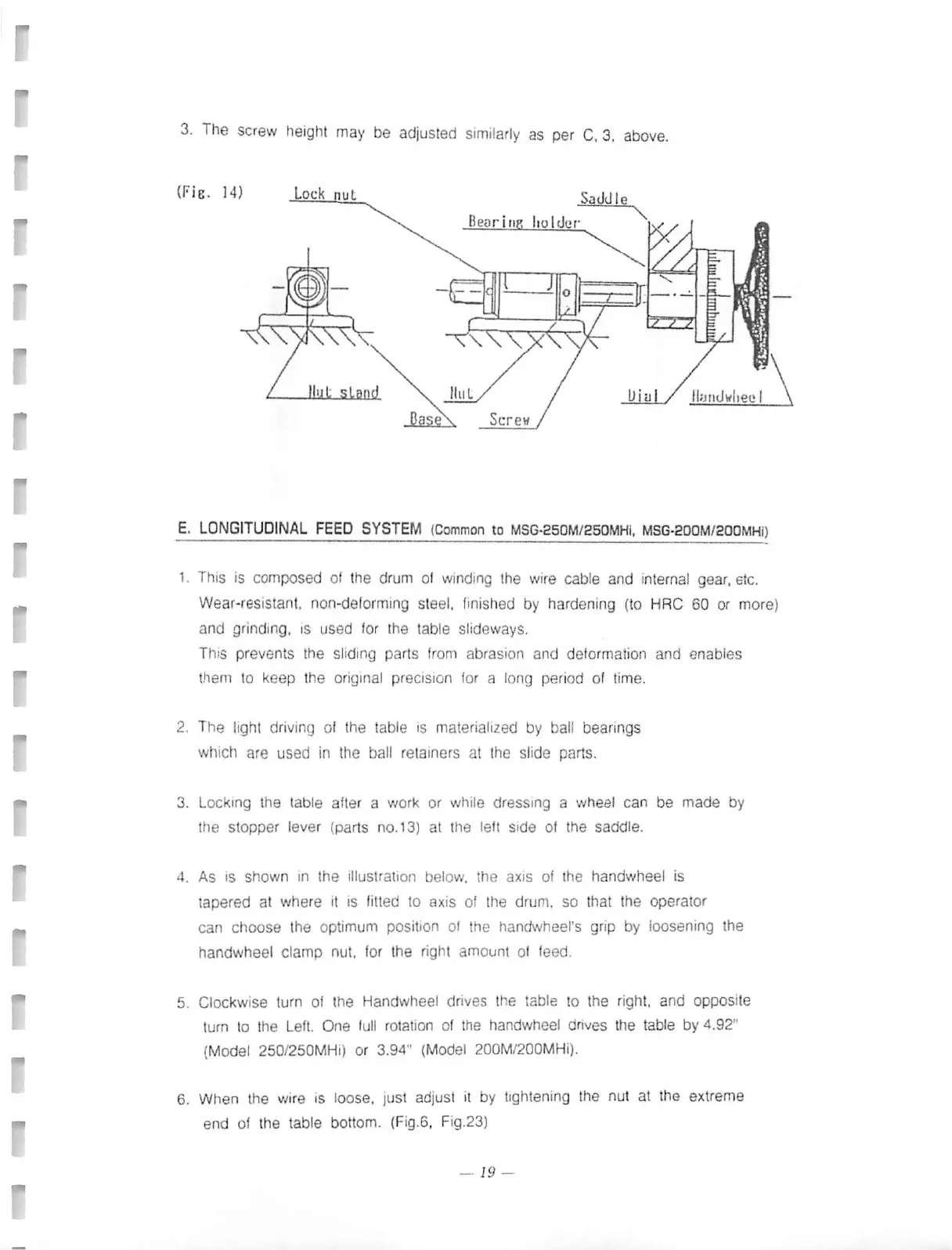
(Fig. 14)
Lock nut
Saddle
\\
Bearing holder
Ni I
Screw
E. LONGITUDINAL FEED SYSTEM (Common to MSG-250M/250MHI, MSG-200M/200M141)
1 This is composed of the drum 01 winding the wire cable and internal gear, etc.
Wear-resistant, non-deforming steel, finished by hardening (to HRC 60 or more)
and grinding, is used for the table slideways.
This prevents the sliding parts from abrasion and deformation and enables
them to keep the original precision for a long period of time.
2. The light driving of the table is materialized by ball bearings
which are used in the ball retainers at the slide parts.
3. Locking the table after a work or while dressing a wheel can be made by
the stopper lever (parts no.13) at the left side of the saddle.
4. As is shown in the illustration below, the axis of the handwheel is
tapered at where it is fitted to axis of the drum, so that the operator
can choose the optimum position of the handwheel's grip by loosening the
handwheel clamp nut, for the right amount of feed.
5. Clockwise turn of the Handwheel drives the table to the right, and opposite
turn to the Left. One full rotation of the handwheel drives the table by 4.92"
(Model 250/250MHi) or 3.94" (Model 200M/200MHi).
6. When the wire is loose, just adjust it by tightening the nut at the extreme
end of the table bottom. (Fig.6, Fig.23)
— 19 —
 Loading...