15
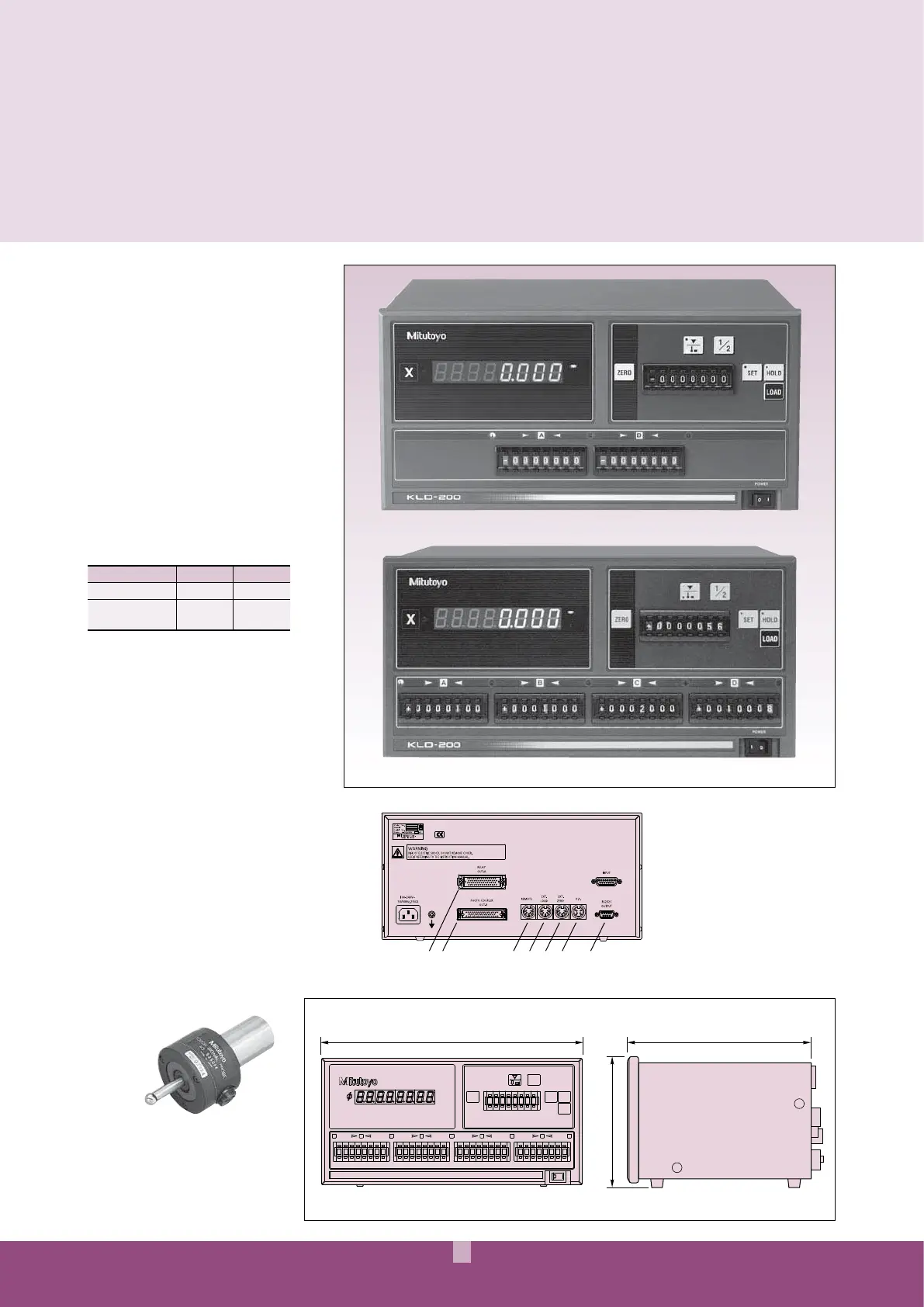
Display Unit
332 204
163
1
A
2
B
3
C
45
D
KLD200
0000000
000 0000000000000000000000
-
000
---
-
1/2
LOAD
HOLD
SET
ZERO
mm
E
12 3 4 5 6 7
Touch-signal probe
Makes it easy to perform such operations as
datum point setting (detecting the workpiece
edge and setting the counter display to
zero), workpiece centering, and dimensional
measurement (detecting the workpiece end point
and holding the counter display).
FEATURES
s¬!¬AXIS¬COUNTER¬DEDICATED¬TO¬
sending signals when a linear scale
displacement value and a preset limit
value coincide.
s¬4WO¬TYPES¬OF¬LIMIT¬SETTINGS¬ARE¬
AVAILABLE¬ ¬STEP¬AND¬¬STEP
s¬&OR¬CONTROLLING¬THE¬VERTICAL¬POSITION¬OF¬
an EDM or grinding machine head.
s¬# AN¬BE¬CONNECTED¬TO¬A¬PERSONAL¬
computer or a sequencer via an
RS-232C interface or limit signal
output (standard feature)
Optional Accessories
965004: External load foot switch
937326: External load box
936551: External zero-set box
938140: Touch-signal probe
¬ SHANK¬DIA¬ MM
935094: Touch-signal probe
¬ SHANK¬DIA¬ MM
902329: Touch-signal probe
¬ SHANK¬DIA¬
DIMENSIONS
5NIT¬MM
KLD-200 Counter
SPECIFICATIONS
Order No. 174-146 174-147
Limit signal output 2-step 4-step
Limit value setting
method
Digital
switch
Digital
switch
* To denote your AC line voltage add the following suffixes to the order
.O¬EG¬174-146A¬ A for UL/CSA, D for CEE, E¬FOR¬"3¬DC for China,
K for EK, No suffix¬IS¬REQUIRED¬FOR¬*)36
Technical Data: Common
,IMIT¬SIGNAL¬OUTPUT¬ STEP¬STEP
3CALE¬INPUT¬PORTS¬
2ESOLUTION¬ MM¬ MM¬ MM
¬ MM¬MM¬ ¬¬ ¬
¬ ¬ ¬ ¬ ¬¬
¬
$ ISPLAY¬ DIGIT¬,%$ ¬AND¬A¬NEGATIVE¬;=¬SIGN
,IMIT¬VALUE¬SETTING¬METHOD¬$ IGITAL¬SWITCH
0OWER¬SUPPLY¬ 6 6¬!# ¬( Z
-ASS¬ KG
174-146 (2-step model)
174-147 (4-step model)
¬2ELAY¬SIGNAL¬OUTPUT
¬0HOTOCOUPLER¬SIGNAL¬OUTPUT
¬2EMOTE¬SIGNAL¬INPUT
¬%XTERNAL¬LOAD¬SIGNAL¬INPUT
¬%XTERNAL¬ZEROSET¬SIGNAL¬INPUT
¬4OUCH¬SIGNAL¬INPUT
¬23 # ¬INTERFACE
¬2ELAY¬SIGNAL¬OUTPUT
 Loading...