17
Display Unit
Counts
up
810
00
8
10
20 10 20 10
60
4
321
1
2
3
4
Tool (1)
Tool (2)
Tool (3)
Tool (4)
Touch
signal
probe
Counts up
Datum
plane (0)
Offset value
Work
piece
Machine table
1 2
3
4
5
Workpiece
Touch signal probe
Datum plane
Workpiece
Machine table
X
0
Scale reference point
Start point (x, y)
Evenly divide by n
End point (x, y)
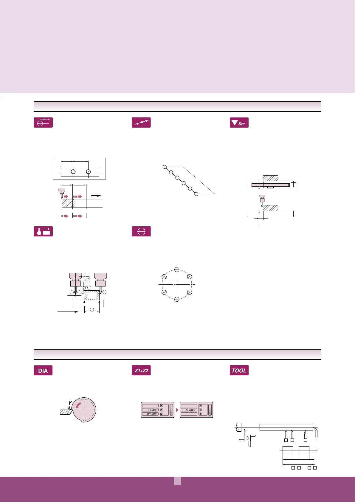
Zero approach machining
[INC mode]
:ERO¬APPROACH¬MACHINING¬CAN¬BE¬REPEATED¬AT¬PRESET¬
intervals. Since the counter keeps the total displacement
in absolute coordinates, a positioning error made by the
operator at one tooling position has no effect on the
remaining positions.
Diameter display
The doubled scale displacement can be displayed. This
convenient function can be used to display the diameter
of a workpiece during a turning operation.
Bolt-hole circle machining
In milling, the drilling positions along the circumference
of the base circle in the absolute zero approach
mode can be easily displayed by entering the center
coordinates, diameter, and number of divisions of the
base circle.
Touch-signal probe
The optional touch-signal probe makes it easy to
perform such operations as datum point setting
(detecting the workpiece edge and setting the counter
display to zero), workpiece centering, and dimensional
measurement (detecting the workpiece end point and
holding the counter display).
Memorization of machining
reference point for each
cutting tool (for KA counter)
Absolute coordinate and incremental coordinate can be
switched by every one of four cutting tools. The counter
can memorize the center of a machining workpiece as
a reference point and it can display the diameter of the
machine workpiece by using absolute coordinate. The
counter can zeroset/preset at the arbitrary position by
using incremental coordinate.
Scale reference point setting
4HE¬LINEAR¬SCALE¬HAS¬SCALE¬REFERENCE¬POINTS¬AT¬MM¬
intervals. When one of the points is detected, the linear
scale issues a signal to hold/restart counting. If the
distance from a scale reference point to the machine
origin is registered as the offset value, it will be retained
even when the power is off (hold function). When the
power is turned on, the machine origin or machining
datum can be easily recalled (set function).
Addition of 2-scale data
The sum of the displayed values of two axes can be
displayed. If a machine has two feed components, fine
feed and coarse feed, each with its own scale, this
function can be used to sum the two feed values.
Pitch machining
"ORES¬HOLES¬BETWEEN¬TWO¬ARBITRARY¬POINTS¬ON¬THE¬89¬
PLANE¬AT¬EQUAL¬SPACES¬"Y¬INPUTTING¬THE¬NUMBER¬OF¬HOLES¬
and positions of the start and end points, holes can
be bored easily at equal spacing. Errors due to table
positioning by the machine are automatically corrected
to the next target value.
LATHE FUNCTIONS
MILLING MACHINE FUNCTIONS
 Loading...