3) Low battery alarm
If the battery voltage becomes considerably low, the LED display blinks red and the U-WAVE-T sends
a low battery alarm error to the U-WAVE-R. Immediately replace the battery.
(The buzzer type alarms a low battery voltage with a buzzer sound along with a blinking LED.)
In addition, the battery (CR2032) used as the power supply for the U-WAVE-T has such a property that
the battery voltage is abruptly restored in a period when the battery has been exhausted, if
measurement data is consecutively transmitted at intervals of several seconds. In such cases,
although low battery alarm errors are not output, the LED display becomes dark and the buzzer sound
becomes small gradually. In such cases, replace the battery immediately.
IMPORTANT
• Always use the CR2032 battery (lithium battery).
• The battery supplied at the time of purchase is to check the functions and performance of the
U-WAVE-T. The predetermined length of life may not be met.
• Even for the used CR2032 battery, its voltage may recover in a short time after it is removed from
the U-WAVE-T. However, do not continue to use the old battery. Be sure to replace the battery
with a new one.
• Upon disposal of the battery comply with the related ordinance, regulation, etc.
• When removing or setting the battery, exercises care so as not to break or bend the battery terminal
by applying an undue force to it. Especially, if a broken piece of the battery terminal should enter
the U-WAVE-T, a failure may be caused.
[3] Connect the Connecting cable to U-WAVE-T
• After loaded with the battery, connect the connecting cable (option, details see section 8)
IMPORTANT
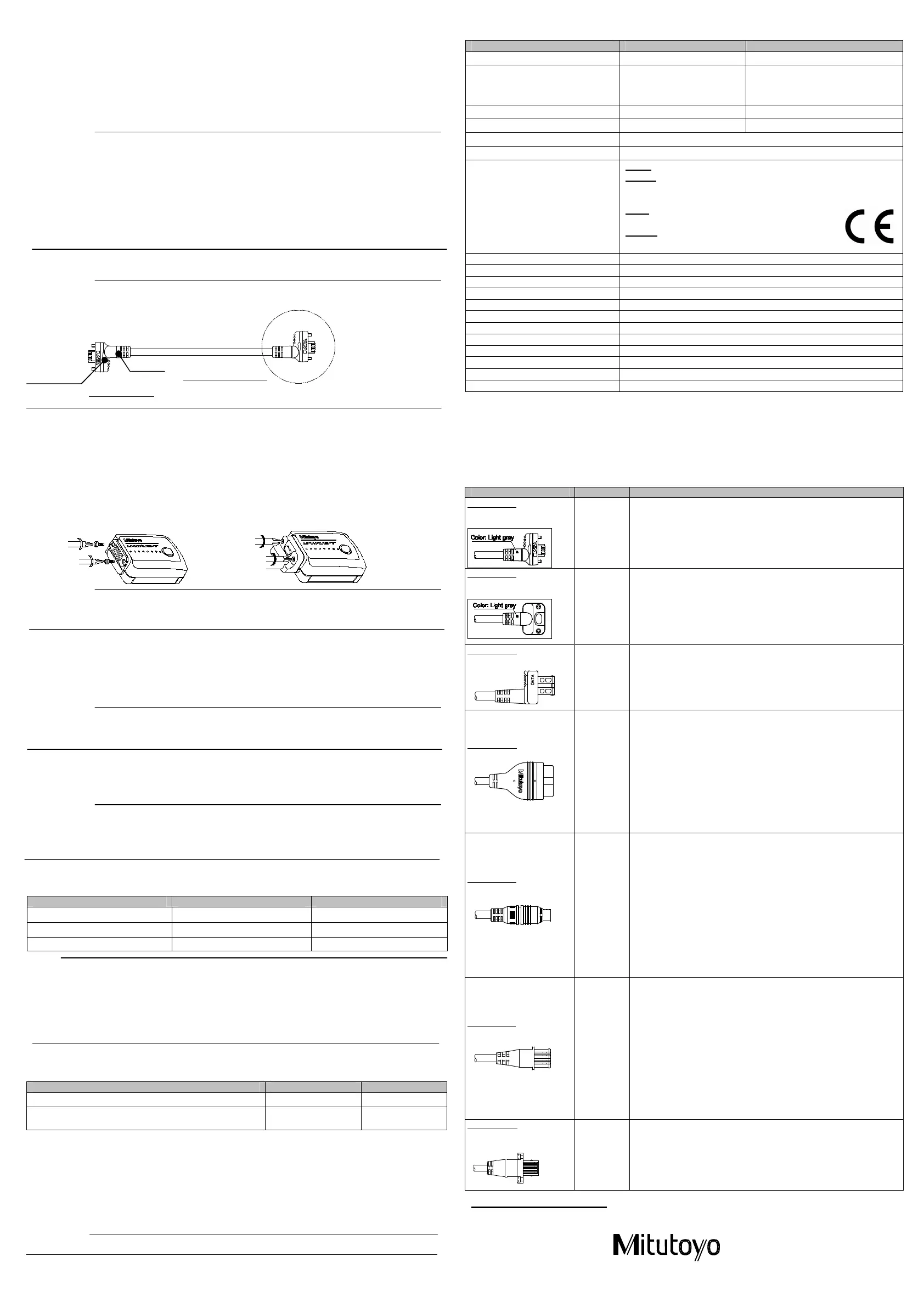
When installing the U-WAVE-T using the connecting cable (02AZD790A, B), particularly
pay attention to the cable orientation. If the cable is connected in the reverse orientation,
data cannot be transmitted.
Black-marked side => U-WAVE-T
Gray-marked side => Measuring tool
• Set up the connecting cable with the following procedure.
When screwing or unscrewing the screws, always use the size 0 screwdriver of the
standard accessory and tighten or loosen them with a torque of 5 to 8 N•cm.
(1) Remove the two mounting screws (M1.7X0.35X2.5/No.A115-1712C) of the connector cover with
the size 0 screwdriver.
(2) Dismount the connector cover.
(3) Check that the packing (No. 09GAA374) has been attached correctly to the specified position.
(4) Connect the connecting cable with the U-WAVE-T.
(5) While pressing the connecting cable end with fingers, tighten the cable fixing screws so that no gap
appears between the cable connector and the U-WAVE-T.
(6) Make sure that no part of the packing is detached.
(1) (5)
IMPORTANT
Do not connect the connecting cable forcibly in a state that the packing (No. 09GAA374) is not in the
correct position on the U-WAVE-T body. Otherwise, the packing may be damaged so that a failure
may be caused.
[4] Register the setting information of U-WAVE-R
After loaded with the battery and connected to a connecting cable, the U-WAVE-T needs to register the
setting information of U-WAVE-R.
Please read the “U-WAVEPAK User’s Manual“ in “PDF_Manual” folder of the CD supplied as a standard
accessory of U-WAVE-R for a detailed registering method and content.
“Adobe Reader” of Adobe Systems INC. is necessary to read.
IMPORTANT
• “Registering the setting information” should be performed by DATA switch of the connecting
cable before connecting to the Measuring tool.
• The registered information is stored after changing battery.
[5] Connecting to Measuring tool
• After registering the setting information, connect the U-WAVE-T to the Measuring tool.
• Clamp the cable leading to a Measuring tool using the supplied cable clamp or a Velcro fastener so
that measurement is not interfered and the LED display of the U-WAVE-T can be easily viewed.
IMPORTANT
• Exercise great caution about the cable routing,
Cable may be disconnected from the instrument or connection part may be damaged
if the excessive force is applied when the cable is snagged to the workpiece, etc..
• Tighten the connecting cable (02AZD790A, B, G) to the Measuring tool with the screw surely.
[6] Functions
1) Data communication
The U-WAVE-T performs data communication with DATA switch as shown below.
Operations DATA switch push-down time t
LED
Transmits measurement data. t ≤ 2sec None
Transmits the Cancel command. 2 sec < t ≤ 5 sec Orange blinking
Executes U-WAVE-R search. 5 sec < t ≤ 10 sec Orange blinking
NOTE
• The Cancel command is a command to inform a U-WAVE-R of data error when wrong measurement
data is transmitted to the U-WAVE-R due to an operating error. However, the wrong measurement data
is not canceled by the command. It is to inform that the previous data is different from measuring value.
• When the U-WAVE-R search is executed, U-WAVE-T is connected with U-WAVE-R that
can be registered.
• If the DATA switch is held down for more than 10 seconds, the orange LED stops blinking and nothing
will function.
The U-WAVE-T can check whether to have performed normal communication with a U-WAVE-R
by a specific LED display (and buzzer sound).
However, buzzer sounds are available only for the buzzer type U-WAVE-T.
Description of state LED Buzzer sound
Wireless communication has been properly completed. Green LED blinking
Short 2 times
• Wireless communication has failed.
• An error has occurred.
Red LED blinking Long 1 time
2) Initializing the setting information
If communication is disabled while using the U-WAVE-T, first refer to Troubleshooting
In U-WAVE-R User’s Manual, if communication is still disabled, initialize the setting information
registered in section 4 to default settings, and then retry communication.
Initialize the setting information with the following procedure.
(1) Remove the battery being loaded. For information about how to remove the battery, refer to section 2.
(2) While holding down the DATA switch on the connecting cable connector, reload the battery in
place. The setting information is initialized.
(3) Remount the battery cover, and set up the U-WAVE-T.
IMPORTANT
Once initialization is performed, the setting information used until then is all cleared.
[7] Specifications
Model IP67 type Buzzer type
Code No. 02AZD730D 02AZD880D
Certification number
005WWCA0166(Japan)
VXU-02AZD730D (U.S.A)
4396B-02AZD730D (Canada)
005WWCA0168(Japan)
VXU-02AZD880D (U.S.A)
4396B-02AZD880D (Canada)
Protection class IP67 -
With/without buzzer Without With
Transmission output Less than 1 mW (0 dBm)
Distance of communication Approx. 20 m (line-of-sight distance under office environments)
A Conformity standard
Japan ARIB STD-T66
Europe EN 50371:2002
EN 300 440-1 V1.3.1 and EN 300 440-2 V1.1.2
EN 301 489-01 V1.6.1 and EN 301 489-03 V1.4.1
U.S.A ・47 CFR Part 15.247:(Subpart :C)
・47 CFR Part 15,(Subpart :B)
Canada・RSS-210 (Issue 7) and RSS-Gen (Issue 2)
・ICES 003 (Issue 4)
Wireless communication protocol IEEE802.15.4 compatible
Communication frequency 2.405 to 2.475 GHz
Used band 15 channels (at intervals of 5 MHz)
Modulation method DSSS (Direct Sequence Spread Spectrum)
Wireless communication speed 250 Kbps
LED display Green/orange/red: 3 discrete color display
Battery CR2032 (3V): 1 piece
Battery life 400,000 times
Operating temperature (humidity) 0 to 40°C (20 to 80%RH, with no condensation)
Storage temperature (humidity) -10 to 60°C (20 to 80%RH, with no condensation)
External dimensions 44 X 29.6 X 18.5 (mm)
U-WAVE-T mass Approx. 23 g
○ Standard accessories
・User’s manual (this manual) No. 99MAL108B ・Precaution for the battery No.99MAL111W
・Size 0 screwdriver No. 05CZA619 ・Lithium battery ・ CR2032C(B)N ・Warranty card
○ Optional accessories No. 02AZD790A to G: Connecting cables (For details see section 8.)
[8] Connecting Cables
As for connecting cables, it is necessary to select a cable compatible with a Measuring tool to be used.
Use an appropriate connecting cable from among those in the following table.
U-WAVE-T side
Measuring tool side
(The connector shape and color differs depending on the
Measuring tool to be used. )
Black
DATA switch
Parts No. Model Series No,
Product Name
02AZD790A
Water-resistant type
with data out switch type
500
500
571
572
573
ABS Coolant Proof Caliper CD-PMX/PM/GM
Super Caliper CD-SPM
ABS Coolant Proof Depth Gage VDS-PMX
ABS Coolant Proof Digimatic Scale Units SD-G
ABS Coolant Proof Exclusive Caliper NTD-PMX/PM
02AZD790B
Water-resistant type with
data out switch type
293
293
---
329
350
---
468
Coolant Proof Micrometer MDC-MJ/MJT
Coolant Proof Micrometer MDE-MJ
Coolant Proof Exclusive Micrometer (The end of the mark is –MJ)
Depth Micrometer DMC-M
Coolant Proof Digimatic Micrometer Heads MHN-M/MJ/MJN
Digimatic Exclusive Micrometer (The end of the mark is –M/PM)
Digimatic Holtest HTD-R
02AZD790C
With data out switch type
500
571
572
500
---
ABS Digimatic Caliper CD-CX/C
ABS Digimatic Depth Gage VDS-/DCX/DC
ABS Digimatic Scale Units SD-D/SDV-D
ABS Digimatic Caliper CD-SC
ABS Digimatic Exclusive Caliper (The end of the mark is –CX/C)
02AZD790D
10 pins type
178
179
515
518
519
542
543
544
544
572
574
Surftest SJ-201/301/401/402
Digi-Derm DGE
CERA Height Master HMD-C
QM-Height QMH-S
Digital Mu-Checker M
Display Unit EB/EC-D
Digimatic Indicator ID-H/ID-F
Laser Scan Micrometer LSM-9506
Laser Scan Micrometer LSM-6200/6900
(It applies when using Digimatic Codeout unit.(02AGC840))
Difference/Sum Unit SD-U1
Heightmatic HDF
02AZD790E
6 pins type
164
227
227
293
---
293
---
339
337
468
515
568
810
810
Digimatic Micrometer Heads MHD-M
Digimatic Micrometer Heads CLM-MH
Soft-Touch Micrometer CLM
Quickmike MDQ
Exclusive Quickmike (The end of the mark is –QM)
Digimatic Micrometer MDC-M
Digimatic Exclusive Micrometer (The end of the mark is -DM)
Digimatic Tubular Inside Micrometer IMJ-M
Digimatic Tubular Inside Micrometer IMZ-M
Digimatic Holtest HTD
Digital Height Master HME-DM
ABS Borematic SBM-C
Hardness Testing Machine HM-100/200/HV-100/HH-411
Rockwell Type Hardness Testing Machines HR-500
02AZD790F
A flat form straight type
192
500
511
543
543
550
551
552
570
547
572
574
575
811
Digimatic Height Gage HDM-A/HD-A
Digimatic Caliper CD
ABS Digimatic Bore Gage CG-D
ABS Digimatic Indicator ID-S
ABS Digimatic Indicator ID-C
Digimatic Caliper CD
Digimatic Caliper CD
Digimatic Carbon Fiber Caliper CFC
ABS Digimatic Height Gage HDS-HC/C
ABS Digimatic Depth Gage
ABS Digimatic Scale Units SD-E/SDV-E/SD-V/SDV-F
Heightmatic HDF-N
ABS Digimatic Indicator ID-U
Hardness Testing Units HH-300
02AZD790G
Water-resistant type with
flat form straight type
543 ABS Digimatic Indicator ID-N/ID-B
Mitutoyo Corporation
20-1, Sakado 1-Chome, Takatsu-ku, Kawasaki-shi, Kanagawa 213-8533, Japan
KAWASAKI,JAPAN
 Loading...