Page 8 MLCS Marvel 60
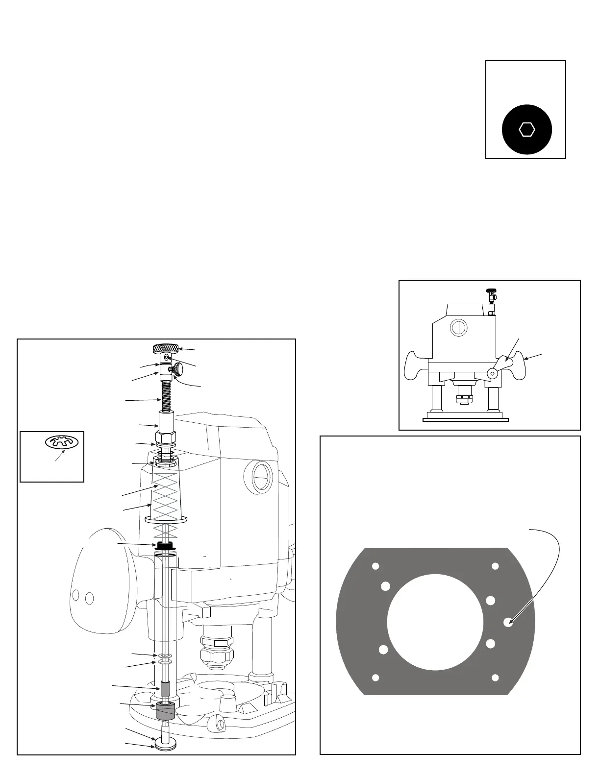
Locate raizer access point on original subbase.
Drill a 3/4" hole through subbase
Access hole Drill 3/4"
10. To ease router raizer adjustments, using fig ( 8 ) slide the small tail of the plunge lock lever spring off the aluminum boss, allowing the
handle to remain in the unlocked position.
fig 8
1. Use #46 locating pin to locate the Router Raizer access hole on the original subbase or router table. For detailed instructions see page 4.
© 2000-2006 Router Technologies
All Rights Reserved
8. Select #12 green bushing ( Two #15 retainers ) #21 lead screw, #22 rapid collar, #23 O-ring, #24 thumb screw,
#26 top drive, #27 yellow set screw, #28 Allen wrench, red grease. Using ( fig 6 ) place grease on threads of
#21 lead screw, Place lead screw down #1 mainshaft and thread into #19 short nut until one inch of mainshaft
extends above the head #21 lead screw. Alignment of #1mainshaft and #21 screw hex is required ( fig 7 ).
Tip: # 29 speed wrench can be used to speed threading.
fig 9
fig 7
Top veiw of #21 lead
screw and #1 main-
shaft through center.
Black Plastic
Plunge Lock
Lever
Handle
Sub-base Plate or Router Table Insert Plate Installation
3. Periodic inspection and re-greasing of #21 lead screw is recommended.
9. Press #23 O-ring onto #24 thumb screw shaft. Thread thumb screw into #22 rapid collar. Place rapid collar onto
#1 mainshaft 1/2" from top of mainshaft to top of rapid collar and tighten ( fig 6 ). Release plunge lock and slowly
raise the router until lead screw contacts the rapid collar. If the collar moves, reset to 1/2". Place one #15 retainer
teeth up on top of #1 mainshaft, using #12 green bushing as installation tool press retainer into contact with
collar,repeat with second #15 retainer and press flush with first retainer. Return # 12 green bushing to box.
Place #26 top drive onto #1 mainshaft until it contacts retainer clip, Thread #27 yellow set screw into #26 top drive
using #28 allen wrench and tighten. Reinstall motor brushes
2. See pages 4-5-6 for further instruction, #30 dust cover insert and #31 dust cover, are router table only. Drill a 1/2" hole through insert plate at
the Raizer access point and press #30 in from top until flush. # 31 sets in #30 and is removed during adjustments with magnet on back edge
of #29 speed handle. These components keep dust from entering the Router Raizer hex drive.
#21 lead screw
#19 short drive nut
#23 O ring
two #15 retainer clips
#26 top drive
#22 rapid collar
#27 yellow set screw
black spring cover
#15 retainer clip
#10 black bushing
drill to 21/64
#1 mainshaft
#7 brass washer
Original Top Spring
#18 drive nut
washer
#40 housing
bushing
#9 red bushing
#15 retainer clip
install teeth up
#14- 3/16 steel washer
fig 6
original spring bushing
 Loading...