Zero Downtime Power Switching (ZDT)
When users connect DC12V power jack and the RJ-45 port at the same time, the power input comes from the DC12V
connector. If the DC12V power source fails, the camera will switch power input seamlessly to the RJ-45 port until
the DC12V power source is restored.
Ethernet Cable Connection
Connect one end of the Ethernet cable to the RJ-45 connector of the camera, and plug the other end of the cable
to the network switch or PC.
NOTE: In some cases, Ethernet crossover cable might be needed when connecting the camera directly to the PC.
NOTE: Check the status of the link indicator and activity indicator LEDs. If the LEDs are unlit, please check the
LAN connection.
Green Link Light indicates good network connection.Orange Activity Light flashes for network
activity indication.
NOTE: The ITE is to be connected only to PoE networks without oute plant or equivalent description.
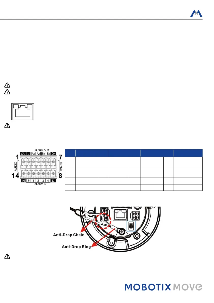
Audio/AIarm I/O & RS485 Connection
Please refer to the diagram and pin definition tables below for audio/alarm I/O & RS485 connection.
Pin Definition Pin Definition Pin Definition Pin Definition
1 Audio Out 5 Alarm Out
B1
9 Alarm In 4 13 GND (Alarm I/O
and RS485)
2 GND (Audio
I/O)
6 Alarm Out
B2
10 Alarm In 3 14 Audio In
3 Alarm Out A1 7 RS485 D+ 11 Alarm In 2
4 Alarm Out A2 8 RS485 D- 12 Alarm In 1
Camera Installation Notice
NOTE: For safety concern, it is recommended to hook up the camera with the anti-drop chain of the pendant
when installing the camera. For more information about pendant and anti-drop chain, please contact the
camera manufacturer.