34 20’ Predator
6KRUWHQWKHGULYHOLQHSURÀOHVDVIROORZV
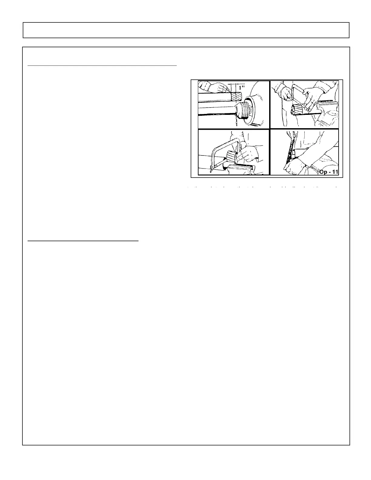
• Remove the driveline from the tractor.
• Position the cutter to the point with the
shortest distance between the tractor
PTO shaft and cutter gearbox. Shut down
WKHWUDFWRUDQGVHFXUHO\EORFNWKHFXWWHU
in this position.
3XOOGULYHOLQHDSDUWDQGUHDWWDFK\RNHWR
PTO shaft.
• Hold driveline sections parallel to one
DQRWKHUDQGPHDVXUHEDFNµIURP\RNH
RIHDFKVKDIWDQGSODFHPDUNRQRSSR
site section. Cut this length off with
a saw.
• Round off all sharp edges and debur.
• Thoroughly grease then reinstall the
driveline.
5HFKHFNIRUSURSHURSHUDWLRQ
Engagement Check Procedure
• With the driveline attached, position the cutter to the point where the telescoping driveline
is at its maximum extension. Completely shut down the tractor and secure in position.
0DUNWKHLQQHUGULYHOLQHVKLHOGµIURPWKHHQGRIWKHRXWHUVKLHOG
• Disconnect the driveline from the tractor and separate the two driveline halves.
0HDVXUHWKHGLVWDQFHIURPWKHPDUNWRWKHHQGRIWKHLQQHUSURÀOH7KLVOHQJWKLVWKHDPRXQW
WKHGULYHOLQHSURÀOHVZHUHHQJDJHG
• If the engaged length is less than 12” for a CV driveline and less than 6” for a non-CV driv
eline, the shaft is considered too short and should be replaced with a longer shaft. Consult an
DXWKRUL]HGGHDOHUWRSXUFKDVHWKHUHTXLUHGGULYHOLQHOHQJWK
127(,IWKHGULYHOLQHFDQQRWEHVKRUWHQHGDQGVWLOOPDLQWDLQWKHUHTXLUHGSURÀOHHQJDJHPHQWWKHRSHUDWRUPXVW
be made aware of terrain conditions and avoid situations which pose a potential problem to avoid damaging
the driveline.
tth it h thtl i di li i tit i
OPERATION
 Loading...