User Instructions
Modulift UK Ltd tel: 011 44 1202 621511 email: sales@modulift.com www.modulift.com
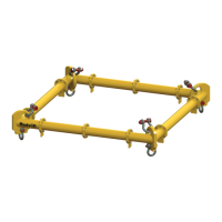
The CMOD Spreader Frame is modular in span and every frame consists of 4 Corner Units,
with intermediate Struts that can be bolted into the assembly to achieve dierent spans.
Personnel using this system should be suitably trained, competent and have a clear
understanding of Safe Slinging procedures.
The use of Modulift equipment must be in accordance with the procedures laid down in ‘ASME B30.20 - 2013’.
Never exceed stated SWL – Adhere to SWL in Table 2 for particular sling angle used.
The top sling length is critical to the safe use of the spreader – Ensure you refer to the correct table.
WARNING!
Assembled
Frame
α
Table 1 – Component List
CMOD 12 Spreader Frame
CMOD 12 Frame Specication
Rated at a maximum of 16 tonnes SWL.
Please see Table 2 for SWL at specic spans.
‘Base to Sling’ angle, α, no less than 45 degrees.
Corner Units are rated at 4 tonnes each
(16 tonnes combined capacity).
Bolt tightening torque: 66 Pound-Foot. Spanner size required: 19mm.
Recommended additional equipment: Torque Wrench, Podger Spanner and Ring Spanner.
CMOD 12 has an assembled span ranging from 2ft by 2ft to 13ft by 13ft in 1ft increments.
P7P2–P5
Span
P6
P1 P8
Strut Corner Unit
Part Ref. Description Weight/item
P1 Corner Unit
(length 1ft each) 50 lbs
P2 5ft Strut 41 lbs
P3 3ft Strut 28 lbs
P4 2ft Strut 21 lbs
P5 1ft Strut 14 lbs
P6 8.5t Shackle 5.7 lbs
P7 6.5t Shackle 3.9 lbs
P8
M12 x 35, Grade 8.8, HT Bolts, Nuts & Washers
α = Base to sling angle (BSA)
Fig. 1 – Typical CMOD Spreader Frame Assembly