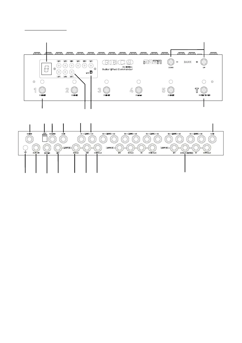
Rear Panel
1- Overview
1
2
3
4
5
Top Panel
6
11
12
16
17
18
19
7
9
8
10
10
151413
(1) PRESETS
These switches immediately recall the settings stored in the corresponding
PRESET 1-5. All the presets are stored in nonvolatile memory, will not be erased
even without power supply.
(2) MUTE/CLEAN
(3) BANK UP / DOWN
(5) Program Lock Switch
This switch shuts off the LOOP OUT (LOUT1&LOUT2) and switches the
INPUT to CLEAN jack, press it again will get back to normal operation.
BANK UP/DOWN scrolls up/down the bank number, there are 20 banks in total.
Bank 1~20 are displayed as 1 2 3 4 5 6 7 8 9 0 1. 2. 3. 4. 5. 6. 7. 8. 9. 0.
When the switch is at “lock” position, the program buttons are disabled.
Lock the program buttons to avoid mis-programming.
(4) Program Buttons
These buttons turn on / off loop1 to loop9 separately.
(6) BANK DISPLAY
It indicates the bank number.
20