Monogram Systems
COMPONENT MAINTENANCE MANUAL
BASIC PN 15900
38-31-09
Page 706
Feb 23/04
(e) Install spray nozzle (135) with washers (130) on each side, securing it with
cotter pin (125).
(f) Position drive shaft assembly (120) with washer (110) on impeller housing
(115).
(g) Install washer (110), impeller (105), washer (100) and retaining ring (95)
on drive shaft assembly (120).
NOTE: Add washers (110) as required to provide full engagement of motor
drive shaft. Impeller (105) must have a minimum clearance of .005
inch (0,13 mm) between impeller and its housing (115).
(h) Install impeller housing plate (75) with impeller housing (115), using
screws (80), washers (85) and nuts (90) to frame assembly (195).
(i) Install filter basket (60), using washer (70 or –70A) and nut (65).
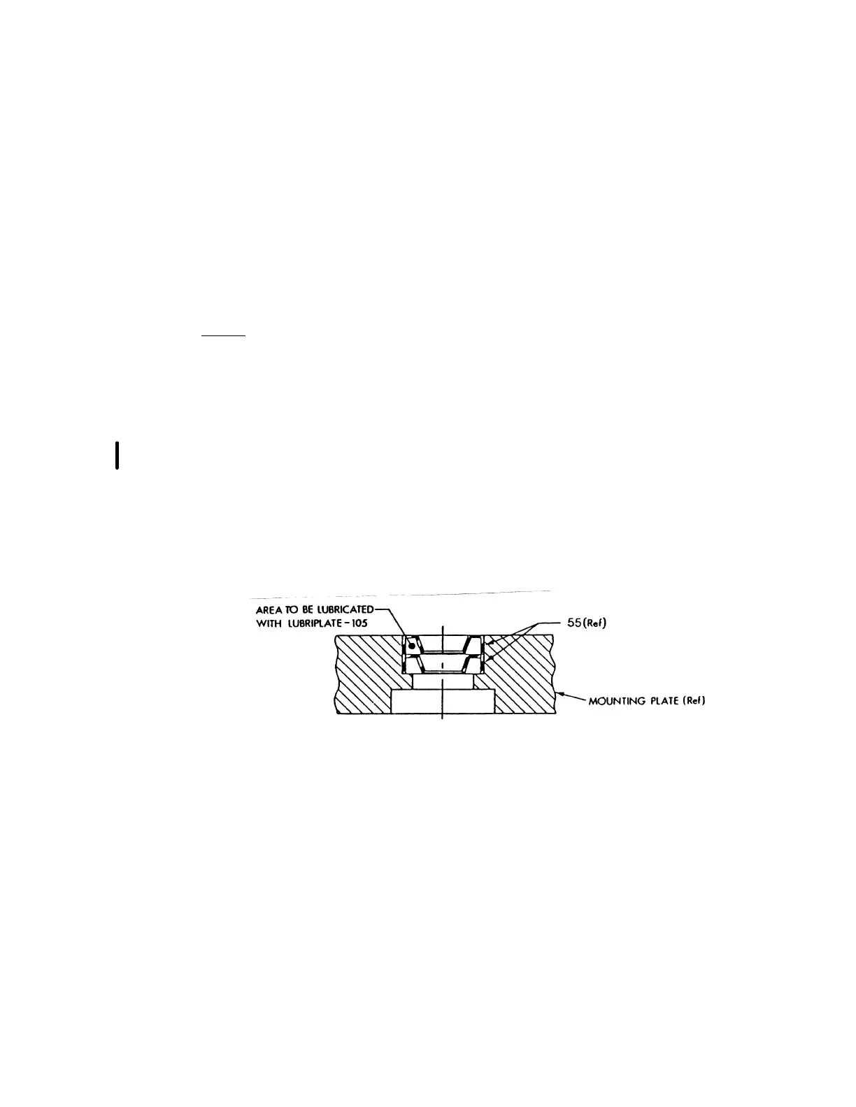
(j) Install seals (55), applying lubricant (Lubriplate 105) as shown in Figure
701.
CROSS SECTION OF MOUNTING PLATE
Figure 701