Do you have a question about the Montarbo W20A and is the answer not in the manual?
Read safety instructions carefully before operating to protect yourself and avoid warranty invalidation.
Product has no user-serviceable parts; refer servicing to qualified personnel.
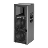
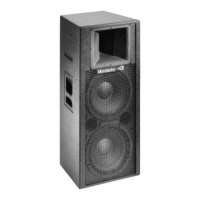
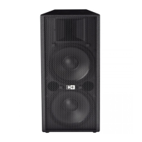
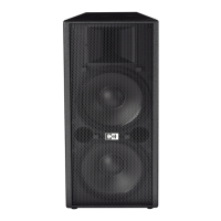
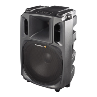
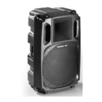
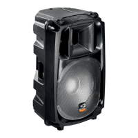
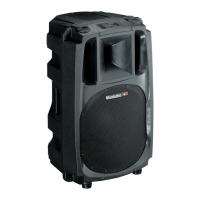
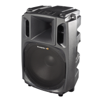
Details the physical construction, components, and design features of the W20A.
High-grade birch plywood construction with phenolic glue and polyurethane paint.
Constant directivity horn with 60°x40° dispersion and 2" dynamic driver.
Features two 10-inch high efficiency woofers for bass frequencies.
Powder-coated, perforated steel grid for driver protection.
Bass reflex enclosure with tuning ports for enhanced low-frequency response.
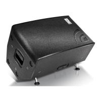
Side recessed handles for easy portability and handling.
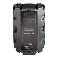
Identifies the location of the rear control and connection panel.
Integrated adapter for mounting the speaker on a standard stand.
Details XLR/Jack parallel input/output sockets for flexible connectivity and daisy-chaining.
Adjusts the input levels of the two built-in power amplifiers for mixer output matching.
Control for adjusting the high frequencies level, with recommended setting for OdB mixers.
The main power switch for turning the unit on and off.
Lifts signal ground from chassis to reduce hum caused by ground loops.
IEC power socket for mains connection, includes a built-in fuse.
Avoid heat, direct sunlight, moisture, dust, and electromagnetic interference for longevity.
Ensure system is off, voltage matches, and use a grounded three-wire cord.
Use shielded cables, switch off before connecting, and follow specific instructions for balanced/unbalanced outputs.
Use heavy gauge, shielded cables for parallel connections, either XLR or Jack.
Detailed specifications for the W20 A speaker system.
Visual representation of the internal signal flow and components.
Explains the various connector types used on the system.
Illustrates typical connection scenarios for the W20 A.
Lists available spare parts for the W20 A speaker system.
Lists the components of the 2-way bass reflex speaker system.
Details the specifications of the 10-inch woofers used in the system.
Details the specifications of the 2-inch driver and horn.
Lists the impedance for bass and mid/high frequency sections.
Provides the frequency response range for the system.
Specifies the sensitivity of the speaker system.
Indicates the maximum Sound Pressure Level achievable.
Details the crossover frequency and slope of the internal crossover.
Lists the maximum output power for bass and mid/high amplifiers.
Overall frequency response of the combined bass and mid-high sections.
Specifies the input impedance of the speaker system.
Indicates the required input signal level for nominal output.
Specifies the noise level referred to the input.
Specifies voltage and frequency for Europe and Asia.
Specifies voltage and frequency for USA and Canada.
Specifies the fuse rating for Europe and Asia.
Specifies the fuse rating for USA and Canada.
Lists the types of balanced inputs available.
Describes the materials and finish used for the enclosure.
Provides the width, height, and depth of the speaker system.
Specifies the total weight of the speaker system.
Shows the connection of the 10" 8-ohm woofer.
Illustrates the connection of the second 10" 8-ohm woofer.
Depicts the connection of the DE750 driver and ME60 horn.
Shows the 24dB crossover network and its role in signal division.
Identifies the power supply unit within the system diagram.
Shows the location of the power switch in the block diagram.
Indicates the fuse within the block diagram.
Illustrates the two MOSFET power amplifier stages.
Shows the passive crossover stages after the amplifiers.
Represents the Acoustic System Processor (A.S.P.) stages.
Indicates the limiter circuits within the amplifier paths.
Shows the input volume control in the signal path.
Represents the balanced input stage of the system.
Shows the link output/input connections for daisy-chaining.
Details the pinout for the balanced XLR male connector.
Explains the standard pinout for balanced connectors (GND, Hot, Cold).
Details the pinout for the balanced jack connector.
Shows the pinout for the balanced XLR female socket.
Shows the pinout for the balanced XLR male socket.
Illustrates the balanced jack sockets on the panel.
Explains the pinout for unbalanced connectors (GND, Hot, Ground).
Illustrates how to connect multiple W20A units in a chain (OUT to IN).
Shows how to connect the W20A input to a mixer's output.
Lists the part number for the 10" high efficiency woofer.
Lists the part number for the DE750 driver.
Lists the part number for the ME60 high frequency horn.
Lists the part number for the 0.7 mH coil.
Lists the part number for the 2-way filter.
Lists components related to the amplifier chassis, like transformer and heat sink.
Lists the part number for the control and connection panel.
Lists the part number for the powder coated steel grid.
Lists the part number for the stand holder.
| Brand | Montarbo |
|---|---|
| Model | W20A |
| Category | Speaker System |
| Language | English |