Industrial Controls Division. Moog Inc., East Aurora, NY 14052-0018. Telephone: 716/652-3000. Fax: 716/655-1803. Toll Free 1-800-272-MOOG.
Moog GmbH. Germany. Telephone: 07031-622-0. Fax: 07031-622-100.
Moog Sarl. France. Telephone: 01 45 60 70 00. Fax: 01 45 60 70 01.
Moog Australia Pty. Ltd. Telephone: 03 9561 6044. Fax: 03 9562 0246.
Moog pursues a policy of continuous development and reserves the right to alter designs and specifications without prior notice. Information contained herein is for guidance only and does not form part of a contract.
Australia: Melbourne, Sydney, Brisbane
Austria: Vienna Brazil: S
~
ao Paulo Denmark: Birkerød England: Tewkesbury Finland: Espoo France: Rungis Germany: Böblingen, Dusseldorf Hong Kong: Shatin India: Bangalore
Ireland: Ringaskiddy
Italy: Malnate (VA) Japan: Hiratsuka Korea: Kwangju-Kun Philippines: Baguio City Singapore: Singapore Sweden: Askim USA: East Aurora (NY)
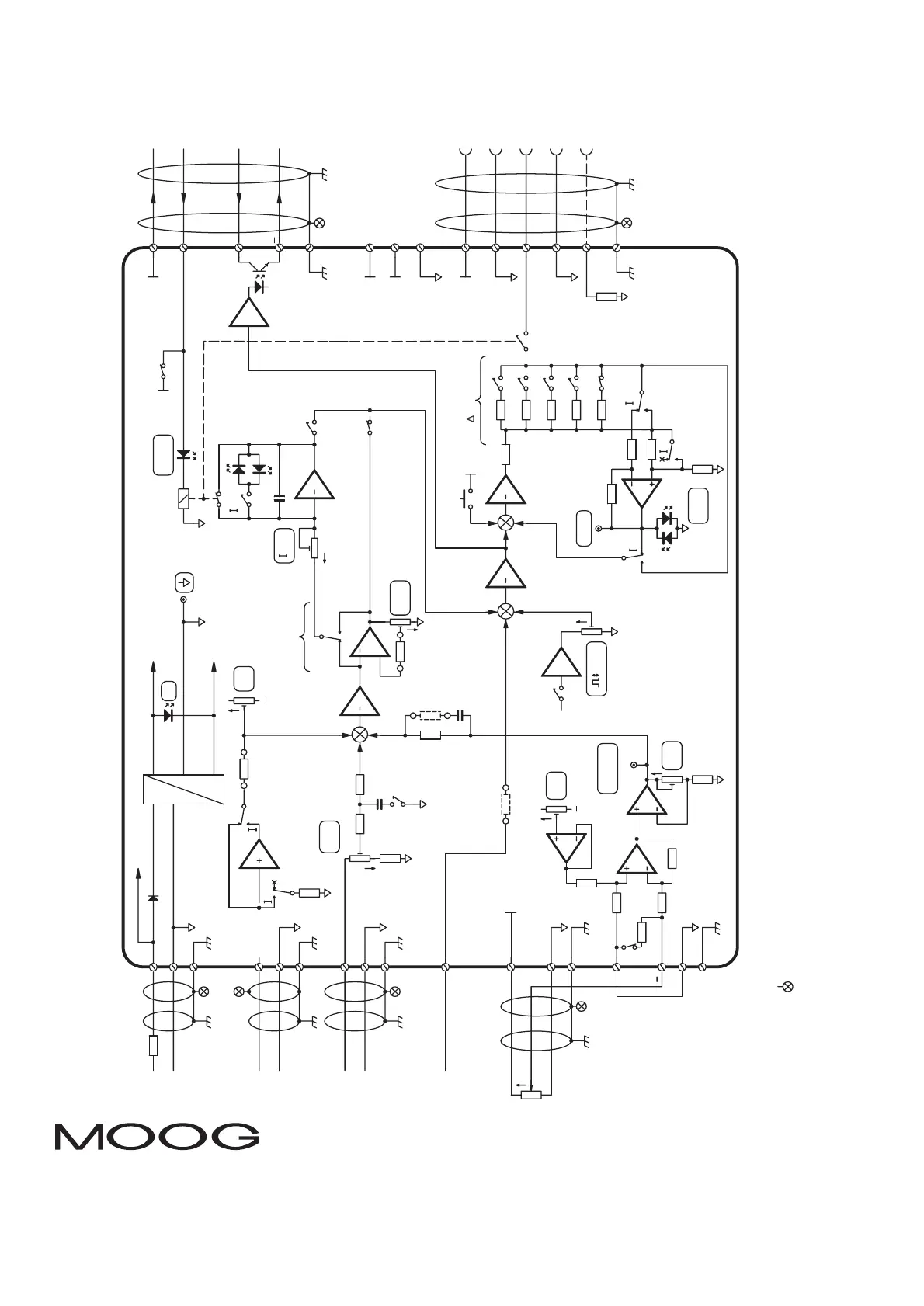
20 Block-wiring diagram
Page 6 of 6: C70861 Rev A – 01.09
+15V
-15
V
T
P
Power Supply
1
2
Output Am p
TP
valv
e
1
1
LED
valv
e
LEDV
s
bias
7
8
100K
6
5
10K
47K 47
K
26
17
18
4-20mA
100K
feedback lead
Feedback Am p
TP
feedbac
k
gain
zer
o
20
19
Transducer
Exc ita tio
n
+
dither
Dither
Oscillator
dither
Error A mp
Av=1
Pgai
n
LED
enabl
e
EP
gai
n
PGainAmp
Integrator
INT
P
R
In Pos itio n
Comparato
r
12
3
4
31
32
22
23
24
100
R
scal
e
Integrator input
selec
t
cmd la
g
N.F.
R16
N.F.
R1
7
100K
R3
4
9
+24V
0V
Supply
16
signal
0Vref
Input 2
13
signal
0Vref
Input 1
27
+10V
0V
Typica
l
Feedback Input
see note 1
see note 1
see note 1
see note
1
+
see note 1
PLC
+24V
Enable
+24V
In positio
n
see note 1
13
10
B
D
E
F
A
efb Valve
Typical D66X
Prop. valve
spool
see note 2
mfb Valve
Connect to
Note: 1. Connect cable screen to enclosure cable gland
or chassis ground terminal on G122-829-001
.
+24
V
25
0Vre
f
1K
+24V
+24
V
14
+15
V
15
-15
V
28
li
m
2.2u
F
+10V
+
Note: 2. Connect spool (pin F) to terminal 22,
only if the spool signal is a current.
pins 31 & 32
.
+
+
4-20mA
-50%
Step P.B.
R33
5mA
10mA
20mA
30mA
50m
A
+24V
enabl
e
Converter
240R
100K
100K
100K
100
K
200R
100R
51R
33R
20
R
V
V
V
V= 1V
39R
Note: 3. Switches shown in default shipping mode.
Av=10
240R
linear pot
feedbac
k
21
V
V
Input 3
Sum &
Limit A m
p
signal
250mA
Tfus
e
+
-
+
SW5
SW5
SW4-1
SW6-3
SW6-4
SW6-2
SW4-2
[SW1-4]
[SW1-3]
[SW1-2]
SW3
SW1-X
SW2
SW2
SW2
Note: 4. [ ] indicates bottom board.
 Loading...