46
© 2011 Skier’s Choice, Inc.
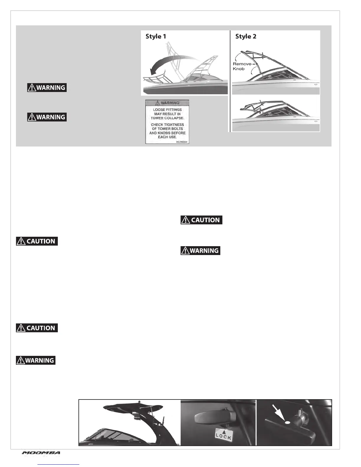
sTYle 1
T
o loWeR CaGe foR sToRaGe:
Tools required: 5/16” Allen wrench (for stainless steel 3/8-16 X
1-14” Allen head bolt)
Loosen, but DO NOT remove front leg allen bolts.
Loosen and remove the hand-knob bolts that connect the
rear legs to the feet.
Place the hand-knob bolts somewhere for safe storage.
While standing in the bow area, pull the cage forward, gently
placing it against the bow of the boat.
Place padding between the cage and the boat to protect
the gel coat.
•
•
•
•
RaD-a-CaGe
To RaIse CaGe:
Lift and rock the tower back into place until the rear legs
align with the rear feet. (Some manipulation of the cage may
be required to get the legs to line up with the feet.)
Install and tighten the rear head-knob bolts
Tighten the front leg’s allen bolts.
The threads in the aluminum foot could be damaged if the
bolts are not aligned and threaded correctly.
The Rad-A-Cage is designed to pull a single (1) wakeboarder,
trick skier, or kneeboarder.
•
•
•
sTYle 2
To loWeR CaGe foR sToRaGe:
Remove the four hand knobs from the top of the rear leg.
While holding the tower up, lower the side legs. Then lower
the tower downward into the boat.
•
To RaIse CaGe:
- Lift the tower and swing up the rear legs. Install the four
hand knobs.
The threads in the aluminum foot could be damaged if the
bolts are not aligned and threaded correctly.
The Rad-A-Cage is designed to pull a single (1) wakeboarder,
trick skier, or kneeboarder.
NOTE: Apply a thin coat of anti-seize to the threads of the
hand knobs periodically.
The Moomba models are equipped with
a Moomba Rad-A-Cage towing tower.
The cage is designed as a stable tower to
enhance wakeboarding. It is NOT intended
to be used to tow skiers, barefooters, or
multiple wakeboarders. Such use will void
any warranties written or implied.
Be sure that all bolts are tightly in place
before use.
Be aware of and avoid low overhead
objects such as bridges, power lines,
overhanging trees, etc.
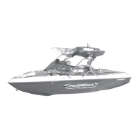
V2 ToWeR
To lower the V2 tower, twist the release handle until the white
dot is facing up. Pull the locking pin out. Repeat on other
side. Guide the tower lower. The tower mechanism does have
mechanical spring assist system to help minimize the eff ort
required to lower the tower.
To raise the V2 tower, guide the tower into the upright position.
Install the locking pin with the white dot up. Push the locking
pin all the way into the tower and then rotate the handle so
the white dot is facing down. Repeat on other side. The tower
mechanism does have mechanical spring assist system to help
minimize the eff ort required to raise the tower.
Warning: Do not operate the boat without the locking pins
properly installed
V2 ToWeR