Please read these instructions carefully before
installing your lighting system. This kit is not
designed to be expanded. Do not add lights,
higher watt bulbs, or additional cable to the kit.
Bulbs should be replaced with 4-watt wedge
base bulbs only.
TOOLS NEEDED:
• Phillips head screw driver
• Flat head screw driver
• Wire cutters (optional)
• Black electrical tape
Remove all items from the carton and check
against the parts list. All parts are approved
for year-round use.
PARTS LIST
1. 1 Control Unit Assembly
2. 50 Feet 12 gage low voltage cable
3. 1 Plastic Anchor
4. 1 #8 mounting screw
5. 10 lighting head caps
6. 10 lighting head lenses
7. 10 lighting head rings
8. 10 4-watt bulbs
9. 10 lens bases
10. 10 cam connectors
11. 10 light poles
12. 10 light stakes
STEP 1 – INSTALL CONTROL UNIT
A. Determine placement of control unit
near outdoor GFCI rated outlet. Control
unit must be installed vertically on a
wall or post at least 24” above ground.
Ensure that there is not a source of light
near control unit to interfere with photo
eye operation (security light, porchlight,
orrstinstalledlightoncable).
B. Attach the female connectors on the
end of the low voltage cable to the
male connectors on the bottom of the
control unit (as shown in Figure 1).
C. If mounting on wood, use a large
screw to attach the control unit through
the bracket provided on the top of the
unit. If mounting on concrete or brick,
drill a 0.6 cm (3/16”) hole and insert
plastic anchor.
D. Lay down your low voltage cable to its
full length in the desired location. You
may bury the cable after installing light
xtures.Excesscablemaybecutoff.
OPERATION:
This control unit includes a photo eye and is
fully automatic. After proper installation, the
control unit will automatically turn the lights on
at dusk and will turn them off when the photo
eye senses light.
STEP 2 – LAMP HEAD ASSEMBLY
To avoid shorting out the control unit, install
alllightxturesonthecablewithpoweroff.
A. Install ring onto lens. Slide ring onto
lens as shown in Figure 2.
B. Turn the lens over and slide the cap
onto the large open end as shown in
Figure 3.
STEP 3 – ASSEMBLE AND
INSTALLATION OF LIGHTS
It is highly recommended that each light unit
be assembled and tested for operation before
moving on to the next light.
A. Start with the light closest to the control
unit. Pick up the cable at the point where
youwishtoplaceyourrstlight.Loop
the cable as shown and squeeze cable
together at the top of the loop as shown
in Figure 4.
B. Slide the pole over the looped end of
the cable as shown in Figure 5.
C. Push the looped cable into the open
bottom of the lens as shown in Figure 6
sothattheatsideofthecablerestsup
against the two spiked terminals that
protrude from the inside.
D. Take the small black cam and push it
through the large hole into the lens base
as shown in Figure 7.
E. Ensure that the cable is trapped between
the cam and the spiked terminals. With
aatheadscrewdriver,turnthecam
180 degrees. The cable should now
be securely fastened to the lens base.
To avoid shorting out the control unit,
do not touch screwdriver to metal parts
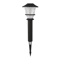
95534 LOW VOLTAGE PATH LIGHT KIT
ASSEMBLY AND INSTALLATION
INSTRUCTIONS:
3 4
6
7
8
9
5
10
11
12
2
1