The Interface Solution Experts 7
TRZ
+
+
TRZ
+PS –PS
TEST TEST
+–
3
+
+
–
–
–
–
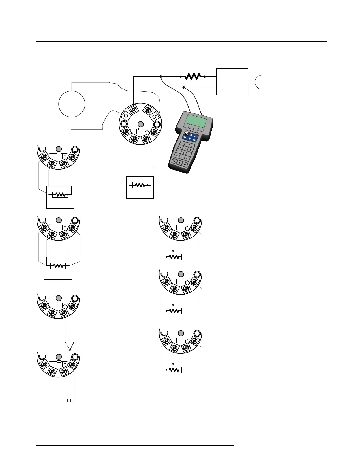
12-28Vdc
POWER
TRZ
LOAD=250 OHMS
THE HART COMMUNICATOR
CAN BE CONNECTED AT ANY POINT
ON THE OUTPUT SIDE OF THE LOOP.
THE TOTAL LOOP RESISTANCE MUST BE
BETWEEN 250 AND 1100 OHMS FOR
GOOD HART COMMUNICATIONS TO
OCCUR.
2-WIRE RTD
OR DECADE
RESISTANCE BOX
OPTIONAL
CURRENT
METER
+–
3
THERMOCOUPLE
SIMULATOR
3-WIRE RTD
OR DECADE
RESISTANCE BOX
+–
3
+–
3
MILLIVOLT
INPUT
4-WIRE RTD
OR DECADE
RESISTANCE BOX
+–
3
2-WIRE
POTENTIOMETER
INPUT
+–
3
3-WIRE
POTENTIOMETER
INPUT
+–
3
4-WIRE
POTENTIOMETER
INPUT
+–
3
Figure 3. Using a HART Communicator to configure the TRZ.