11
NOTE:Ensurewhenroutingthewirenottodamage
thewireterminals.
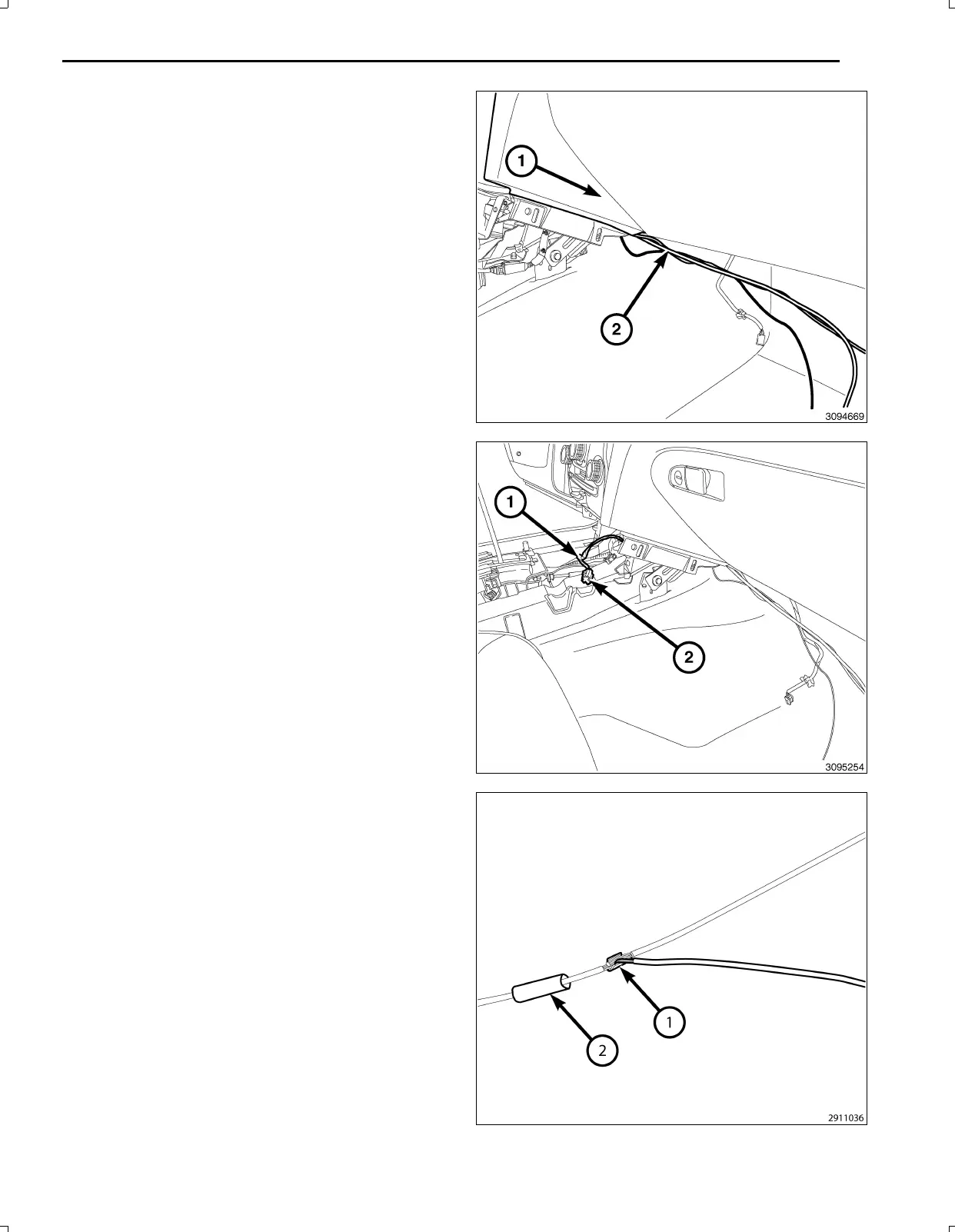
47.Feedthebackupcamerawiringharness(2)through
thelowerI/P(1)forconnectingtothe12Vignition
poweroutletwiringharnessandtheTGM.
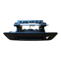
48.Removeenoughoftheinsulatingtape(1)fromthe
wiresofthe12Vignitionpoweroutletwiringharness
connector(2)tospliceintothetwowires.
49.Preparetocrimp/splicethebackupcamerapowerwire
(PK/OR)tothe(DB/PK)ofthe12Vignitionpowerout
letwiringharnessconnectorasfollows:
a.Cutthe12VignitionpoweroutletDB/PKwire.
b.Remove13mm(0.5in.)ofinsulationfromeach
wirethatneedstobespliced.
c.Placeapieceofadhesivelinedheatshrinktubing
(2)ononesideofthewire.Makesurethetubing
willbelongenoughtocoverandsealtheentire
repairarea.
d.Placethestrandsofwireoverlappingeachother
insideofthespliceclip(1).
Nov16,2010K6861117