11
52.Removethe12VignitionpoweroutletfromtheI/P
lowerbinareaasfollows:
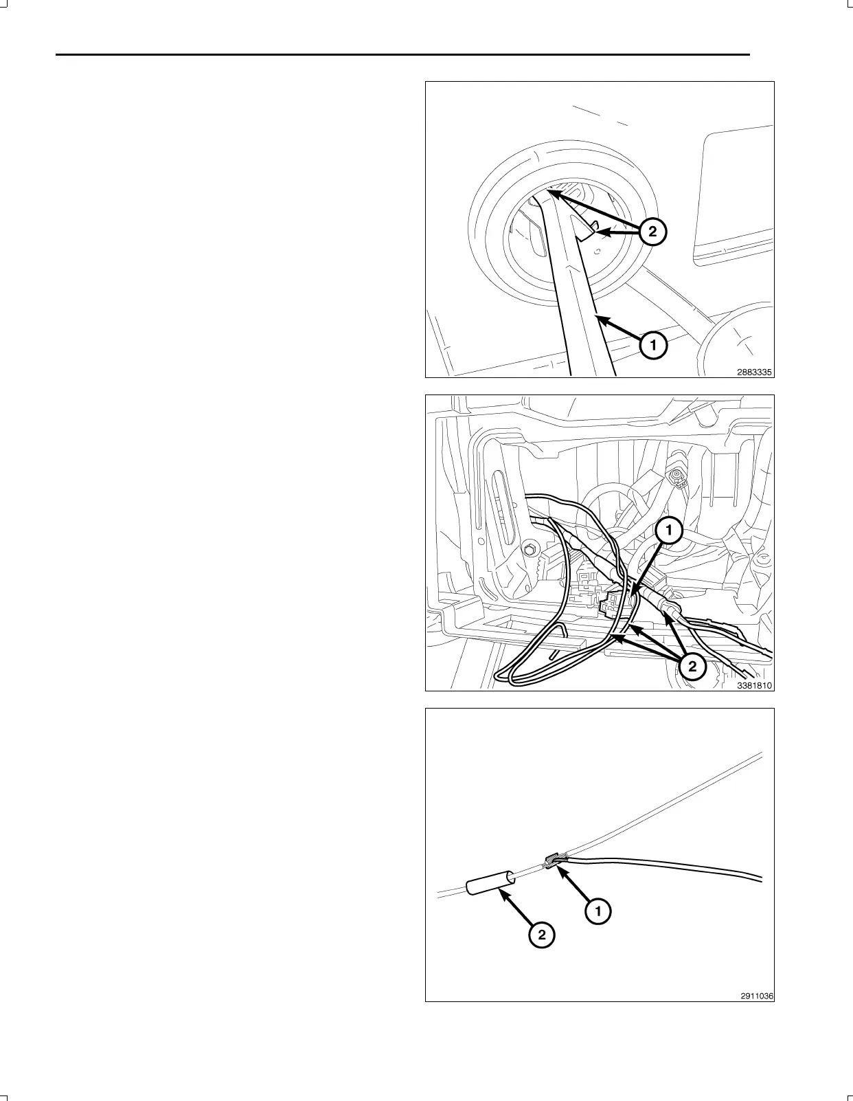
a.Lookinsideandnotepositionoftheretainingbosses
(2).
b.InsertPowerOutletRemover10246(1),orequivalent
intotheretainingbosses(2)ofthepoweroutlet.
c.Pulloutthebasethroughthemountingringbygently
rockingthetool.
d.Disconnecttheharnessfromthepoweroutletandset
theoutletaside.
e.Pullthe12Vignitionpoweroutletwiringharnesscon
nectorthroughtheopeninginthebackofthecenter
stackareaforsplicing.
NOTE:TheI/Pendofthebackupcameraharness(2)
hasthetwowireswithoutterminalendsforsplicing
tothe12Vignitionpoweroutletconnector(1).
NOTE:Ensurewhenroutingthewireharnessnotto
damagethewireterminals.
53.Feedthebackupcamerawiringharness(2)fromthe
LHsideoftheI/Pneartheparkbrakepedaloverthe
brakepedalsledandthroughthelowerI/Pandintothe
centerI/Pstackareaforconnectingtothe12Vigni
tionpoweroutletwiringharnessconnector(2)andthe
TGM.Securetothevehicleharnesswithtiestraps.
54.Removeenoughoftheinsulatingtapefromthewires
ofthe12Vignitionpoweroutletwiringharnesscon
nector(1)tospliceintothetwowires.
55.Preparetocrimp/splicethebackupcamerapowerwire
(PK/OR)tothe(DB/PK)ofthe12Vignitionpowerout
letwiringharnessconnectorasfollows:
a.Cutthe12VignitionpoweroutletDB/PKwire.
b.Remove13mm(0.5in.)ofinsulationfromeach
wirethatneedstobespliced.
c.Placeapieceofadhesivelinedheatshrinktubing
(2)ononesideofthewire.Makesurethetubing
willbelongenoughtocoverandsealtheentire
repairarea.
d.Placethestrandsofwireoverlappingeachother
insideofthespliceclip(1).
Feb02,2011K6861161
 Loading...