This document serves as the Use and Maintenance Manual for the MOSA GE 10000 KD/GS and GE 12000 KD/GS generating sets, with an edition date of March 2014. The manual's code is 259509003.
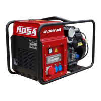
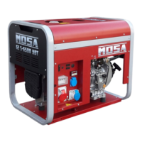
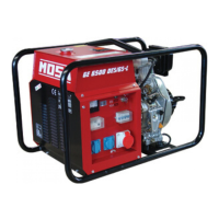
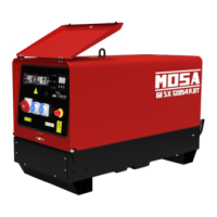
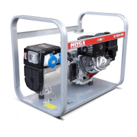
The generating set is a unit designed to transform mechanical energy, produced by an endothermic engine, into electrical energy via an alternator. The assembly is built on a steel structure with elastic supports to dampen vibrations and reduce noise. The unit features a protective closed frame to guard against impacts during handling and transport, with the front panel fully integrated into the structure for component protection. A fuel tank and starter battery complete the main components.
Quality System
MOSA's quality system is certified according to UNI EN ISO 9001:2008, ensuring consistent high quality for its products. This certification covers the design, production, and servicing of engine-driven welders and generating sets. The certifying institute, ICIM (a member of the International Certification Network IQNet), officially approved MOSA after an examination of its operations at the head office and plant in Cusago (MI), Italy. This certification signifies MOSA's commitment to maintaining a high level of quality in products and services, satisfying client needs, and improving transparency and communication in accordance with official procedures and the MOSA Manual of Quality.
Advantages for MOSA clients include:
- Consistent high-level quality of products and services.
- Continuous efforts to improve products and performance under competitive conditions.
- Competent support in problem-solving.
- Information and training for correct application and use of products to ensure operator safety and environmental protection.
- Regular inspections by ICIM to confirm adherence to the company's quality system and ISO 9001 requirements.
Important Notes and Warnings
This manual is a crucial part of the machine. Assistance and maintenance personnel must keep it readily available, along with manuals for the engine and alternator (if synchronous), and all other relevant documentation. Users are advised to pay close attention to safety-related pages. All rights are reserved by MOSA, a division of B.C.S. S.p.A. Reproduction, in whole or in part, is prohibited without written permission from MOSA. MOSA is not responsible for direct or indirect damage resulting from the use of the provided information. MOSA reserves the right to refuse services or information publication deemed questionable, unlawful, or illegal.
The manufacturer is not liable for any use of the product other than what is precisely specified in this manual, nor for risks arising from improper use. The company assumes no liability for damage to persons, animals, or property. Products conform to safety norms, and it is advisable to use all safety devices and information to prevent harm. Personal safety norms (clothing, tools, etc.) should be followed during work. Unauthorized modifications to machine parts (fastenings, holes, electrical or mechanical devices) are prohibited; responsibility for any such intervention falls on the executor.
CE Mark and Noise Level
All MOSA products are CE marked, indicating conformity to applicable directives and safety requirements. The CE marking is clear, indelible, and may be part of the data plate. Each model also displays its noise level (LWA) using a specific symbol, ensuring compliance with the 2000/14/CE directive.
Technical Data
The GE 10000 KD/GS and GE 12000 KD/GS models are available in both single-phase and three-phase configurations.
GE 10000 KD/GS (Single-phase)
- Generator:
- Stand-by single-phase power: 10 kVA (9 kW) / 230 V / 43.5 A
- PRP single-phase power: 9 kVA (8.1 kW) / 230 V / 39.1 A
- Frequency: 50 Hz
- Cos φ: 0.9
- Alternator: Self-excited, self-regulated, brushless synchronous, single-phase, Insulation class H.
- Motor:
- Make / Model: Kohler KD 425/2
- Type / Cooling system: Diesel 4-Stroke / air
- Cylinder / Displacement: 2 / 851 cm³
- Stand-by net power: 11.5 kW (15.6 HP)
- PRP net power: 10.5 kW (14.3 HP)
- Speed: 3000 rpm
- Fuel consumption (75% of PRP): 2.2 l/h
- Engine oil capacity: 1.8 l
- Starter: Electric
- General Specification:
- Fuel tank capacity: 18 l
- Running time (75% of PRP): 8.2 h
- Protection: IP 23
- Dimensions (LxWxH): 935x580x645 mm
- Weight: 159 Kg
- Acoustic power LwA (pressure LpA): 99 dB(A) (74 dB(A) @ 7 m)
GE 12000 KD/GS (Three-phase)
- Generator:
- Stand-by three-phase power: 12 kVA (9.6 kW) / 400 V / 17.3 A
- PRP three-phase power: 11 kVA (8.8 kW) / 400 V / 15.9 A
- Stand-by single-phase power: 6 kVA / 230 V / 26 A
- Frequency: 50 Hz
- Cos φ: 0.8
- Alternator: Self-excited, self-regulated, brushless synchronous, three-phase, Insulation class H.
- Motor: (Same as GE 10000 KD/GS)
- General Specification: (Same as GE 10000 KD/GS, except weight)
Output Power Definitions:
- Declared power: According to ISO 8528-1 (temperature 25°C, 30% relative humidity, altitude 100 m above sea level).
- Stand-by power: Maximum available power for variable loads, limited to 500 hours yearly. No overload admitted.
- Prime power (PRP): Maximum available power for variable loads, unlimited hours yearly. Average power over 24 hours must not exceed 80% of PRP. 10% overload is admitted every 12 hours.
- Derating: Approximately 1% reduction per 100 m altitude and 2.5% per 5°C above 25°C.
Acoustic Power Level:
The concrete risk from the machine depends on usage conditions. The end-user is responsible for evaluating this risk and adopting precautions (e.g., Individual Protection Device).
- LWA (Acoustic Noise Level): Acoustic noise released over time, not dependent on measurement distance.
- Lp (Acoustic Pressure): Pressure from sound wave emission, changes with distance.
- Lp at 1 meter (LWA 95 dB(A)): 87 dB(A)
- Lp at 4 meters (LWA 95 dB(A)): 75 dB(A)
- Lp at 7 meters (LWA 95 dB(A)): 70 dB(A)
- Lp at 10 meters (LWA 95 dB(A)): 67 dB(A)
The LWA symbol with acoustic noise values indicates compliance with noise emission limits per 2000/14/CE directive.
Installation and Advice Before Use
- Gasoline and Diesel Engines: Use in open, well-ventilated spaces, allowing exhaust gases (containing carbon monoxide) to dissipate away from the work area.
- Airflow: Ensure complete air exchange and prevent hot exhaust air from re-entering the set, which could cause dangerous temperature increases.
- Stability: Secure the machine with tools or devices to prevent movement during operation.
- Movement: Before moving, ensure the engine is off and all cables are disconnected.
- Placement: Place the machine on a level surface at least 1.5 m from buildings or other plants.
- Environmental Conditions: Do not install the machine in flood-prone areas or use it in weather conditions beyond its IP protection rating (specified on the data plate and in the technical data section).
- Maximum Leaning: The maximum allowable lean for the machine is 20° (α and β).
Unpacking
- Lifting Devices: Ensure lifting devices are correctly mounted, adequate for the machine's weight with packaging, and conform to local regulations.
- Inspection: Upon receipt, check for transport damage, rough handling, or missing parts (envelopes, manuals). Report any issues immediately to Technical Service.
- Packaging Disposal: Dispose of packing materials according to national norms.
- Procedure:
- Remove the machine (C) from its packing.
- Take out the user's manual (B) from envelope (A).
- Read the user's manual (B), machine plates, and data plate.
Transport and Displacements
- Preparation: Always transport with the engine off, electrical cables and starting battery disconnected, and the fuel tank empty.
- Lifting: Ensure lifting devices are correctly mounted, adequate for the machine's weight with packaging, and conform to local regulations. Only authorized personnel should be in the movement area.
- Loading: Do not load other parts that could alter weight or center of gravity.
- Prohibition: It is strictly forbidden to drag the machine manually or tow it with any vehicle (for models without CTM accessory). Failure to follow instructions may damage the machine's structure.
- Weight Limits: Max weight per person: 35 kg. Total max weight: 140 kg.
Assembly (CTM 10)
Lift the machine and assemble parts as shown in the drawing. The CTM accessory cannot be removed from the machine for separate use (manual or vehicle transport of loads) or for uses other than machine movement.
Set-up for Operation (Engine Diesel)
- Battery (Maintenance-Free): Connect the positive (+) cable to the positive (+) pole of the battery (after removing protection) by tightening the clamp. Check battery status via the warning light color: Green (OK), Black (recharge), White (replace). Do not open the battery.
- Oil Bath Air Filter: Fill the air filter with the same engine oil to the indicated level.
- Fuel:
- Refill with good quality diesel fuel (e.g., automobile type). Refer to the motor manual for fuel type.
- Do not fill completely; leave approx. 10 mm space for expansion.
- In cold conditions, use winterized diesel fuels or specific additives to prevent paraffin formation.
- Lubricant (Recommended Oil): MOSA recommends AGIP engine oil. Refer to the motor label for specific products and viscosity.
- Refueling and Control: Perform with the motor level.
- Remove oil-fill tap (24).
- Pour oil.
- Check oil level with dipstick (23); level must be between min/max indicators.
- Caution: Overfilling is dangerous and can cause sudden increases in rotation speed.
- Dry Air Filter: Check for correct installation and absence of leaks to prevent unfiltered air from entering the motor.
- Grounding Connection: Obligatory for models with a differential switch. The generator star point is typically connected to machine earthing. Use terminal (12) and comply with local electrical installation and safety regulations.
Starting and Stopping the Engine
- Daily Check: Perform daily checks.
- Note: Do not alter primary regulation conditions or touch sealed parts.
- Starting Procedure:
- Open the fuel cock.
- Ensure accelerator lever (16) is at minimum setting.
- Turn starter key to "ON." Battery charge and oil warning lights should illuminate.
- Operate the starter: Turn key to "START" and hold until engine starts. If it fails within 5 seconds, release, wait 10 seconds, then try again. Release key to "ON" once started.
- Note: Using the electric starter for more than 5 seconds at a time will overheat and damage it.
- Warm up the engine for 2-3 minutes.
- Use: Before operating, place accelerator lever on "MAX" and keep it there during all work.
- Running-in (Caution): During the first 50 hours, do not exceed 60% of maximum output power. Check oil level frequently. Adhere to engine manual rules.
- Stopping Procedure:
- Emergency Stop: Immediately pull stop lever (28).
- Normal Stop:
- Stop drawing current from auxiliary sockets.
- Set accelerator lever (16) to minimum and wait a few minutes for engine to cool. Follow engine manual instructions.
- Pull stop lever (28) until engine stops.
- Turn key (Q1) to "OFF."
- Shut the fuel cock.
- Safety: For safety, the key must be kept by qualified personnel.
Controls (Refer to detailed legend in manual)
The manual provides a comprehensive list of controls and their functions, including:
- Hydraulic oil level light (B4)
- Welding socket (-) (C2)
- Alternator (A)
- Engine oil reservoir cap (E6)
- Fuel filling cap (F6)
- Muffler (G6)
- Stop control (H6)
- Engine cooling/alternator fan belt (I6)
- Hydraulic oil drain tap (J6)
- Fuel drain tap (K6)
- Exhaust tap for tank fuel (L6)
- Start button (M6)
- Booster socket 12V (N6)
- Battery charge fuse (O6)
- Space for remote control (P6)
- Space for E.A.S. (Q6)
- Space for PAC (R6)
- Electric start socket (S6)
- Reset button PTO HI (T6)
- Quick coupling PTO HI (U6)
- Battery thermal switch (V6)
- Aux current thermal switch (W6)
- Pre-heater spark plugs thermal switch (X6)
- Electropump thermal switch (Y6)
- Choke control (Z6)
- Voltmeter relay (A7)
- Fuel pump (B7)
- Starting push button (C7)
- Operating mode selector (D7)
- Power on warning light (E7)
- Relay (F7)
- Wire connection unit (G7)
- R.P.M. adjuster (H7)
- Fuel valve (I7)
- Insulation monitoring (J7)
- Battery charge light 30 l/1' PTO HI (K7)
- Engine control unit EP2 (L7)
- E.A.S. connector (M7)
- E.A.S. PCB (N7)
- Booster socket (O7)
Using the Generator
- Warning: It is absolutely forbidden to connect the unit to the public mains or another electrical power source. Access to the area adjacent to the electricity-generating group is forbidden for unauthorized personnel.
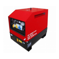
- Canopy Generators: For canopy generator sets with doors, keep engine compartment and electrical box doors closed and locked during normal operation as protection barriers. Access internal parts only for maintenance by qualified personnel when the engine is stopped.
- Electrical Energy Production: Generating groups are electrical energy producing stations. Dangers include electrical energy, chemical substances (fuels, oils), rotating parts, and waste products (fumes, heat).
- AC Generation (Alternating Current):
- Before each session, check the efficiency of the ground connection if required by the distribution system (e.g., TT and TN systems).
- Verify electrical specifications (voltage, power, frequency) of powered units match the generator to prevent damage.
- For three-phase loads, ensure cyclic direction of phases matches installation requirements.
- Connect devices to AC sockets using suitable plugs and cables in prime condition.
- Before starting, ensure no dangerous situations exist.
- Check thermal-magnetic switch (Z2) is in OFF position.
- Start the group, position thermal-magnetic switch (Z2) and differential switch (D) to ON.
- Before powering utilities, check voltmeter (N) and frequency meter (E2) for nominal values. If assembled, check voltmeter change-over switch (H2) for consistent line voltages.
- In absence of load, voltage and frequency may exceed nominal values.
- Operating Conditions - Power: Electrical power (kVA) is available output power under reference environmental conditions and nominal values for voltage, frequency, and power factors (cos φ). Power types (PRP, STAND-BY) are defined by ISO 8528-1 and 3046/1. Never exceed power indications, especially with multiple loads.
- Voltage:
- Compound Setting (Three-phase/Single-phase): No-load voltage is generally 3-5% greater than nominal. Precision is maintained within ±5% with balanced loads and 4% speed variation. Resistive loads may see +10% voltage over-elevation, halving after 10-15 minutes. Full load insertion/release causes transitory voltage variation <10%, returning to nominal within 0.1 seconds.
- Electronic Setting (A.V.R.): Voltage precision maintained within ±1.5% with speed variations from -10% to +30%, and balanced loads. Voltage is same with no-load and load. Full load insertion/release causes transitory voltage variation <15%, returning to nominal within 0.2-0.3 seconds.
- Frequency: Directly dependent on motor rotation speed. Mechanical regulators typically have a droop <5% from no-load to nominal load, maintaining precision within ±1% under static conditions. Electronic regulators achieve ±0.25% precision and constant frequency from no-load to load (isochronal operation).
- Power Factor - Cos φ: Ratio between Active Power (kW) and Apparent Power (kVA). Nominal cos φ is 0.8. Do not exceed declared active power (kW) to avoid overloading. For cos φ <0.8, the alternator must be downgraded.
- Start-up of Asynchronous Motors: Can be critical due to high start-up currents (up to 8 times nominal current). Start-up current must not exceed alternator's admissible overload current (250-300% for 10-15 seconds).
- Precautions: Subdivide multiple motors into groups, start at 30-60 second intervals. Use reduced voltage, star point/triangle, autotransformer, or soft-start systems if machine allows.
- Ensure no other utilities are inserted during asynchronous motor start-up to prevent voltage droop issues.
- Single-Phase Loads (from three-phase generators):
- Voltage tolerance cannot be maintained by the regulator due to system imbalance. Section other loads if necessary.
- Maximum power between Neutral and Phase (star connection) is generally 1/3 of nominal three-phase power (some alternators allow 40%). Between two Phases (triangle connection), max power cannot exceed 2/3.
- Use monophase sockets for connecting loads. Otherwise, use "R" phase and Neutral.
- Electric Protections - Thermal-Magnetic Switch (Z2): Protects against short-circuits and overloads. Do not modify adjustable settings. Intervention is not instantaneous; greater overload means faster intervention. Nominal operating current refers to 30°C; 10°C variation corresponds to 5% variation in nominal current. If tripped, check total absorption does not exceed nominal current.
- Differential Switch (D): Guarantees protection against indirect contacts from malfunction currents to ground. If tripped, check for installation defects (cables, sockets, plugs, utilities). Before each session, test operation by pressing the test key with the generator running and lever in ON position.
- Thermic Protection: Protects against overloads on individual power sockets. If nominal current is exceeded, the device cuts power. Intervention is not instantaneous. If tripped, check load current and allow protection to cool before resetting.
- Usage with EAS Automatic Start-up Panel: Forms a unit for distributing electrical energy within seconds of a power failure.
- Perform connections safely. Position automatic panel in RESET or LOCKED mode.
- First start-up in MANUAL mode.
- Check generator's LOCAL START/REMOTE START switch (16) is in REMOTE.
- Check generator switches are enabled.
- Position EAS panel in manual mode, press MAN. key, then START key after checking for dangerous situations.
- During operation, all controls and signals from both panels are enabled.
- In case of alarm (low pressure, high temperature), the automatic panel indicates malfunction, and the generator's front panel is disabled.
- Attention: Do not forcefully press the central pole of the thermic protection to prevent its intervention.
Trouble-Shooting
- Warning: Qualified personnel must perform maintenance and troubleshooting. Stop the engine before working inside. If operation is necessary, pay attention to moving parts, hot parts (exhaust manifold, muffler), and unprotected electrical parts. Remove guards only when necessary. Wear appropriate clothing and PPE. Do not modify components without authorization.
- Engine Problems:
- Motor does not start/stops immediately: Lack of fuel, clogged filter, air leaks, faulty battery, loose terminals, other causes. Solution: Refill fuel, replace filter, check circuit, activate/recharge battery, tighten/clean terminals, consult manual.
- Motor does not accelerate/inconstant speed/too little power: Air or fuel filter clogged, overload. Solution: Clean/replace filter, check/reduce loads, consult manual.
- Generator Problems:
- Absence of output voltage: Protection tripped, differential device tripped, defective protection devices, alternator not sparked/defective. Solution: Check/diminish load, check installation for defects, replace devices, external spark test, check/repair alternator winding/diodes, contact Service Department.
- No-load voltage too low/high: Incorrect motor running speed, defective alternator. Solution: Adjust accelerator lever, check/repair alternator winding/diodes, contact Service Department.
- Corrected no-load voltage too low with load: Incorrect motor running speed due to overload, load with cos φ less than nominal, defective alternator. Solution: Check/diminish load, reduce/rephase load, check/repair alternator winding/diodes, contact Service Department.
- Unstable tension: Malfunctioning contacts, irregular motor rotation, defective alternator. Solution: Check/tighten electrical connections, contact Service Department for motor rotation, check/repair alternator winding/diodes, contact Service Department.
Maintenance
- Warning: Qualified personnel must perform maintenance and troubleshooting. Stop the engine before working inside. If operation is necessary, pay attention to moving parts, hot parts (exhaust manifold, muffler), and unprotected electrical parts. Remove guards only when necessary. Wear appropriate clothing and PPE (protective gloves, insulated gloves, glasses). Do not modify components without authorization.
- Definition: Maintenance includes verifying mechanical and electrical parts, and fluids subject to use or consumption. This includes periodic fluid changes and refills, and machine cleaning. Repairs (replacement of damaged or consumed parts) are not considered maintenance and should be done by an Authorized Service Center or manufacturer. Tire replacement (for trolleys) is a repair.
- Schedule: Periodic maintenance should follow the engine manual schedule. An optional hour counter (M) is available.
- Important: During maintenance, avoid polluting substances (liquids, exhausted oils) causing harm to people, things, or negative environmental/health effects, respecting all laws.
- Engine and Alternator: Refer to specific manuals provided by each manufacturer for maintenance intervals and checks.
- Ventilation: Ensure no obstructions (rags, leaves) in air inlet/outlet openings of machine, alternator, and motor.
- Electrical Panels: Check cable and connection condition daily. Clean periodically with a vacuum cleaner; do not use compressed air.
- Decals and Labels: Check all warnings and decals annually and replace if missing or unreadable.
- Strenuous Operating Conditions: Perform maintenance more frequently under conditions like frequent stops/starts, dusty environment, cold weather, extended no-load operation, or fuel with over 0.5% sulfur.
- Battery (Maintenance-Free): Do not open the battery. It is charged automatically. Check status via warning light color (Green: OK, Black: recharge, White: replace).
- Note: Engine protection will not work if oil quality is low or not charged regularly as prescribed in the owner's manual.
Storage
- Short-term (less than 30 days): Store in a dry place, protected from heat sources and weather changes. Qualified personnel should prepare the machine.
- Gasoline Engine Storage:
- Run engine until it stops due to lack of fuel.
- Drain engine oil and refill with new oil.
- Pour 10 cc of oil into spark plug hole, rotate crankshaft several times, then screw in spark plug.
- Rotate crankshaft slowly until compression is felt, then leave it.
- If electric start battery is assembled, disconnect it.
- Clean covers and all parts.
- Protect with plastic hood and store in a dry place.
- Diesel Engine Storage:
- Short periods (every 10 days): Run machine with load for 15-30 minutes for lubricant distribution, battery recharge, and to prevent injection system blockage.
- Long periods: Contact after-sales service of the engine manufacturer.
- Clean covers and all parts.
- Protect with plastic hood and store in a dry place.
- Important: During storage, avoid polluting substances (liquids, exhausted oils) causing harm to people, things, or negative environmental/health effects, respecting all laws.
Cust Off (Disposal)
- Procedure: Qualified personnel must disassemble the machine and dispose of parts (oil, fuel, etc.) correctly when taking it out of service.
- Definition: Cust off includes all operations at the user's expense at the end of the machine's life: dismantling, component subdivision for reuse/disposal, packing, and transport to storage or disposal bureau.
- Hazardous Fluids: Operations involve manipulating potentially dangerous fluids like lubricating oil and battery electrolyte.
- Safety: Dismantle metallic parts using heavy gloves and suitable tools to prevent injuries.
- Regulations: Dispose of components according to applicable laws.
- Particular Attention: Pay special attention when disposing of lubricating oils, battery electrolyte, and flammable liquids (fuel, cooling liquid).
- Responsibility: The user is responsible for observing environmental norms regarding machine disposal.
- Compulsory Removal (if not disassembled): Tank fuel, engine lubricating oil, engine cooling liquid, battery.
- Note: The manufacturer is involved in cust off only for non-reparable second-hand machines, after authorization.