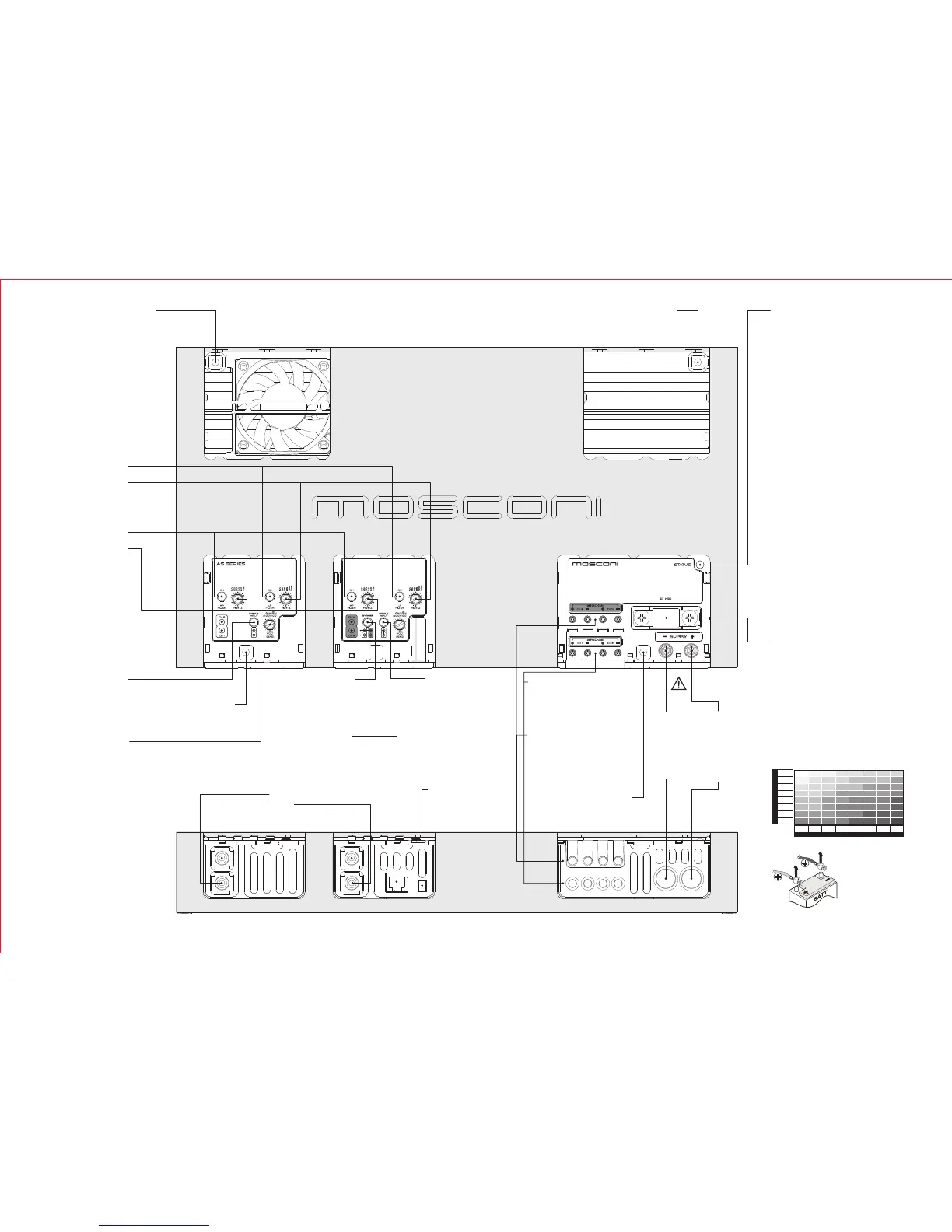
FUSIBILE DI
PROTEZIONE
AS 100.2 40A
AS 200.2 80A
AS 300.2 150A
AS 100.4 80A
AS 200.4 150A
Before replacing the fuse, power off
the audio source and then
disconnect the battery.
Remove the blown fuse and replace
it with the same model and rating
(same maximum amp)
FASTENING HOLES
Use the screws provided in the package
or screws of 4mm diameter. Tighten bolts
to a maximum of 5 Nm torque.
NEGATIVE POWER
CONNETION
Securely connect the
clamp to a metallic part
of the frame or chassis
of the vehicle. Strip the
paint and debris, and
use the shortest
possible cable with the
proper terminal.
POSITIVE POWER
CONNECTION
Connect the clamp to
the positive lead of the
battery. Use the
shortest possible cable
with the proper
terminal. We
recommend using an
external fuse as close
as possible to the
battery.
LOW PASS FILTER
Activate
Control
the low pass filter by pushing
the button
the cut-off frequency of the low-
pass filter by using the
potentiometer (knob)
ATTENTION!
Use power cables with a gauge that is appropriate to the
current load and to the length of the cable. The table in this
manual indicates the minimum gauge for safe use. Whenever
possible, use the largest gauge available.
14/2 12/4
12/4 10/6
10/6
10/6 10/612/4 8/9 8/9 8/9
8/9 8/9
8/9 8/9
8/9 8/9
6/14
6/146/14
6/14 6/14
6/14
6/14
6/14
6/14
6/14
4/21
4/21
4/21
4/214/214/21
4/21
4/21 4/21 4/21
4/21 4/21
4/21
4/21
2/34 2/34 2/34
2/34
2/34 2/34
2/34 2/34
2/34 2/34 2/34
2/34
2/34 2/34
0/54 0/54
0/54
0/54
0/54 0/54
0/54
0/54
0-1.2 1.2-2.1 2.1-3.1 3.1-4.0 4.0-4.9 4.9-5.8 5.8-6.7
0-20
20-35
35-50
50-65
65-85
85-105
105-125
125-150
6.7-8.5
CURRENT (A)
LENGTH (m.)
MIN. SECTION (AWG/mm )
2
RCA SIGNAL INPUT
Channel 1
Channel 2
Channel 3
Channel 4
12V
HIGH PASS FILTER
Activate
Control
the high pass filter by pushing
the button
the cut-off frequency of the
high-pass filter by using the
potentiometer (knob)
BAND PASS FILTER
Activate
Control
both filters to get a band pass
filter
the cut-off frequencies by
using both potentiometers
(knobs)
FASTENING HOLES
Use the screws provided in the package
or screws of 4mm diameter. Tighten bolts
to a maximum of 5 Nm torque.
SINGLE INPUT
Activate
NOTE: use this function only if
there is a single input connected
this button to have the same channel
ch3 signal in channel ch4.
The RCA ch4 may be used as a
channel ch3 bypass.
SINGLE INPUT
Activate
NOTE: use this function only if
there is a single input connected
to the amplifier
this button to have the same channel
ch1 signal in channel ch2.
The RCA ch2 may be used as a
channel ch1 bypass.
FASTENING HOLES
Use the screws provided in the package
or screws of 4mm diameter. Tighten bolts
to a maximum of 5 Nm torque.
GAIN (SENS.)
Adjust
the sensitivity of the amplifier to the
input signal to adapt to the level of
the audio source.
Consult the manual of the audio
source.
BYPASS
Activate
to repeat ch1 and ch2 signals to the
ch3 and ch4 channels respectively.
The RCA of ch3 and ch4 can be used
as bypass of RCA of ch1 and ch2
respectively.
REMOTE POWER CONTROL
Connect the remote power terminal
(+12V) of the source to the FASTON
connector of the amplifier using a
properly terminated cable.
INDICATION LIGHT
RED:
ORANGE:
YELLOW:
1) The loudspeaker system is not connected properly
or is damaged
2) The signal cables from the audio source are not
properly connected or damaged
3) The signal from the audio source is absent or
inadequate
1) Verify/restore the connection and/or replace the
damaged loudspeakers
2) Verify/restore the connection from the audio source
3) Properly adjust the audio source following the
manufacturer's recommendations
1) The amplifier is powering up
2) The temperature has reached the safety threshold
3) Current overload in the loudspeaker circuit
1) Wait 3 seconds, the amplifier will switch to normal
operation
2) Wait for the temperature to decrease
3) Remove the cause of the overload
1) The power supply is inadequate
2) The fuse has blown
3) The power voltage is below 7 VDC
4) The amplifier is malfunctioning
1) Verify and restore the connections and the contacts
of the power circuit
2) Replace the fuse
3) Recharge or replace the vehicle's battery
4) Contact an authorized reseller to initiate the
procedure for Technical Assistance
the amplifier is in operation
Possible causes for lack of sound:
Remedy
the amplifier is in protected mode. After 3
seconds the amplifier attempts to resume automatically
Possible causes:
Remedy:
the amplifier is powered on but is not
functioning.
Cycle the power to verify proper operation.
Possible causes:
Remedy:
REMOTE CONTROL (optional)
Connect
the remote control (optional) terminal
to this connector
SPEAKER CONNECTION
Connect
the speakers to the Ch1 and Ch2 terminals
to reproduce the audio input in the RCA ch1
and ch2 respectively.
Connect the speakers to the BRIDGE
terminals to reproduce a mixed signal from
the RCA ch1 and ch2
SPEAKER CONNECTION
Connect
the speakers to the Ch3 and Ch4 terminals
to reproduce the audio input in the RCA ch3
and ch4 respectively.
Connect the speakers to the BRIDGE
terminals to reproduce a mixed signal from
the RCA ch3 and ch4
FASTENING HOLES
Use the screws provided in the package or
screws of 4mm diameter. Tighten bolts to a
maximum of 5 Nm torque.
WARNING!
DISCONNECT THE
BATTERY LEADS
BEFORE
INSTALLATION,
MAINTENANCE OR
REMOVAL.
 Loading...