PREPARING TO CHARGE:
a) If necessary to remove battery from vehicle to charge, always remove grounded terminal from battery first.
Make sure all accessories in the vehicle are off, so as not to cause an arc.
b) Be sure area around battery is well ventilated while battery is being charged.
c) Clean battery terminals. Be careful to keep corrosion from coming in contact with eyes.
d) Add distilled water in each cell until battery acid reaches level specified by battery manufacturer. Do not overfill.
For a battery without removable cell caps, such as valve regulated lead acid batteries, carefully follow
manufacturer’s recharging instructions.
e) Study all battery manufacturer’s specific precautions such as removing or not removing cell caps while
charging and recommended rates of charge.
f) Determine voltage of battery by referring to car owner’s manual. Do not use the battery charger unless battery
voltage matches the output voltage rating of the charger.
CHARGER LOCATION:
a) Locate charger as far away from battery as dc cables permit.
b) Never place charger directly above battery being charged; gases from battery will corrode and damage charger.
c) Never allow battery acid to drip on charger when reading electrolyte specific gravity or filling battery.
d) Do not operate charger in a closed-in area or restrict ventilation in any way.
e) Do not set a battery on top of charger.
FOLLOW THESE STEPS WHEN BATTERY IS INSTALLED IN VEHICLE. A SPARK NEAR BATTERY MAY CAUSE BATTERY
EXPLOSION. TO REDUCE RISK OF A SPARK NEAR BATTERY:
a) Position ac and dc cords to reduce risk of damage by hood, door, or moving engine part.
b) Stay clear of fan blades, belts, pulleys, and other parts that can cause injury to persons.
c) Check polarity of battery posts. POSITIVE (POS, P, +) battery post usually has larger diameter than
NEGATIVE (NEG, N,–) post.
d) Determine which post of battery is grounded (connected) to the chassis. If negative post is grounded to
chassis (as in most vehicles), see (e). If positive post is grounded to the chassis, see (f).
e) For negative-grounded vehicle, connect POSITIVE (RED) clip from battery charger to POSITIVE (POS, P, +)
ungrounded post of battery. Connect NEGATIVE (BLACK) clip to vehicle chassis or engine block away from
battery. Do not connect clip to carburetor, fuel lines, or sheet-metal body parts. Connect to a heavy gage metal
part of the frame or engine block.
f) For positive-grounded vehicle, connect NEGATIVE (BLACK) clip from battery charger to NEGATIVE (NEG, N,
–) ungrounded post of battery. Connect POSITIVE (RED) clip to vehicle chassis or engine block away from
battery. Do not connect clip to carburetor, fuel lines, or sheet-metal body parts. Connect to a heavy gauge
metal part of the frame or engine block.
g) When disconnecting charger, disconnect AC cord, remove clip from vehicle chassis, and then remove clip
from battery terminal.
FOLLOW THESE STEPS WHEN BATTERY IS OUTSIDE VEHICLE. A SPARK NEAR THE BATTERY MAY CAUSE BATTERY
EXPLOSION. TO REDUCE RISK OF A SPARK NEAR BATTERY:
a) Check polarity of battery posts. POSITIVE (POS, P, +) battery post usually has a larger diameter than
NEGATIVE (NEG, N, –) post.
b) Attach at least a 24-inch-long 6-gauge (AWG) insulated battery cable to NEGATIVE (NEG, N, –) battery post.
c) Connect POSITIVE (RED) charger clip to POSITIVE (POS, P, +) post of battery.
d) Position yourself and free end of cable as far away from battery as possible – then connect NEGATIVE
(BLACK) charger clip to free end of cable.
e) Do not face battery when making final connection.
f) When disconnecting charger, always do so in reverse sequence of connecting procedure and break first
connection while as far away from battery as practical.
g) A marine (boat) battery must be removed and charged on shore. To charge it on board requires equipment
specially designed for marine use.
PRIOR TO USE, READ AND UNDERSTAND PRODUCT SAFETY INFORMATION.
Failure to follow the instructions may result in ELECTRICAL SHOCK,
EXPLOSION or FIRE, which may result in SERIOUS INJURY, DEATH, DAMAGE
TO DEVICE or PROPERTY. Do not discard this information.
KEEP CHILDREN AWAY. This unit is not for use by children and should only
be operated by adults.
USER INSTRUCTIONS
AUTOMATIC CHARGING AND BATTERY STATUS MONITORING:
The MOTOPOWER MP00205B battery chargers are completely automatic and may be left connected to both AC
power and to the battery that it is charging for long periods of time. The charger output power, voltage, and current
depends on the condition of the battery it is charging. It has LED indicator lights that provide a visual means to
determine the operating mode of the charger and hence the condition of the battery connected to the charger.
ATTENTION: The MOTOPOWER® CHARGER HAS A SPARK FREE CIRCUITRY.
The output alligator clips or ring terminals will not spark when they are touched together. The charger will not
produce an output voltage until it senses at least 4 volts from the battery. It must be connected to a battery with the
correct polarity before it will start charging a battery. Therefore, if you plug the AC power cord into an AC power
outlet, and if the output alligator clips or ring terminals are not connected to a battery, and if you touch the alligator
clips or ring terminals together, there will be no electrical spark.
WORKING WITH A DEAD BATTERY OR A BATTERY WITH A VERY LOW VOLTAGE:
If you try to charge a dead battery having a voltage below 4 Volts, the MOTOPOWER® charger will not start. An
internal safety circuit prevents the charger from generating any output voltage unless it senses at least 4 Volts at
the charger output. In this situation, the green power on light will flash, indicating that a charge has not been
initiated.
STATUS INDICATING LIGHTS:
TROUBLESHOOTING CHECK LIST:
1. CHARGER LIGHTS DOES NOT TURN ON:
a. Check to make sure AC outlet is supplying power by plugging in a lamp, an appliance, or a voltage meter.
2. THE GREEN LIGHT GOES ON IMMEDIATELY WHEN CHARGING A DISCHARGED BATTERY:
a. The battery may be defective, take battery to the dealer to be tested.
3. CHARGER IS CHARGING BUT THE GREEN LIGHT DOES NOT GO ON:
a. The battery may be defective, take battery to the dealer to be tested.
b. The battery has an excessive current draw, remove battery from equipment.
MANUFACTURER :
MOTOPOWER INC.
16192 Coastal Hwy, Lewes, DE 19958, USA
www.motopowers.com
EU IMPORTER:
Transrite Industries Co., Limited
12 AV Roland Corrao, 13700 Marignane
FR 60 852111939
Email:sales@transrite.com
Support by Email to -
customerservice@motopowers.com
Copyright MOTOPOWER PRODUCTS
Made In China
SPECIFICATIONS:
Input Voltage:
Output Voltage:
Battery Chemistries:
Battery Capacity:
100-240V AC, 50-60Hz
Wet, Gel, MF, CA, EFB, AGM
2-100Ah Maintains All Battery Sizes
12V DC
Output Current: 1000mA/1Amp
Charged Voltage: 14.2V +/- 0.2V DC
Maintenance Voltage: 13.6V +/- 0.2V DC
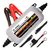
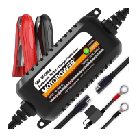
MP00205B BATTERY CHARGER / MAINTAINER 1000
Premium Automatic Battery Charger Series - Optimizer X
Power On - Electric power is supplied to the charger.
Solid Green
Solid Red
Bulk Charge - Whenever the red light is on steady, a battery is connected properly and the charger is charging
the battery.
Pulsing
Yellow
Absorption - When the Yellow light is flashing, the battery is greater than 90% charged and may be removed
from the charger and used if necessary. Different with the bulk charge, a 0.5amp pulse current will be applied to
make sure the battery fully charged in a proper way during this stage. Whenever possible, leave the battery on
charge until the green light is solid.
Pulsing
Red
Desulfating / Soft start - If the battery voltage is below 8volts, the battery charger will start the desulfating mode by
giving a 0.5amp pulse current to optimize the cells and activate the battery softly. The Red LED will flash
indicating the mode. When the battery voltage reaches at 8volts, the charger will enter the normal charging mode.
Solid
Green
CHARGED/MAINTAINING. When the CHARGED green light turns solid, the charge is completed and the
battery can be returned to service if necessary. It can also stay connected to maintain the battery for an
indefinite period of time.
Solid
Yellow
Reverse Polarity Connection. When the charger connects with the battery in the reverse polarity, the top LED
will turn on yellow indicating the connection error.
NOTE: THE OUTPUT CLIPS OR RING TERMINALS MUST BE CONNECTED TO A BATTERY BEFORE THE CHARGER CAN
PRODUCE AN OUTPUT VOLTAGE.
If the charger is hooked up backwards, the LED indicator will not change. The alligator clips or accessory ring
terminals must be connected to the battery, with the proper polarity, Red to Positive (+ output to + battery post)
and Black to Negative (- output to - battery post), before the charger will generate any output voltage.