EasyManua.ls Logo

Motorline professional MC50 - User Manual

Motorline professional MC50
18 pages
Print Icon
To Next Page IconTo Next Page
Loading...
24V
1 2
v1.1 REV. 04/2022
MC50
27042021 | 24092021
EN
Compatible hardware versions:
USER/INSTALLER MANUAL
MC50

Questions and Answers

  • J
    jacob57Aug 8, 2025
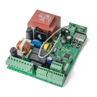
    What to do if Motorline professional MC50 motor doesn't work?
    • D
      David GibsonAug 8, 2025
      First, ensure a 110/230V power supply is connected to the control board and functioning correctly. Then, open the control box to verify the presence of a 110/230V power supply. Check the control board input fuses. If these steps don't resolve the issue, disconnect the control board from the motor and test the motor by connecting it directly to an external power supply to determine if the motor is faulty. If the motor works when connected to an external power supply, send the control board to MOTORLINE technical services for diagnosis. If the motor doesn’t work with external power, send the motor to MOTORLINE technical services for diagnosis.
  • D
    Dennis WilcoxAug 15, 2025
    What to do if Motorline professional MC50 Control Systems motor opens but doesn’t close?
    • J
      James GambleAug 15, 2025
      If the Motorline professional Control Systems motor opens but doesn’t close, check for any obstacles blocking the photocells. Also, inspect the control devices (key selector, push button, video intercom, etc.) to ensure none are jammed and sending a continuous signal to the control board. You can close with a shunt all safety systems on the control board. Remove one shunt at a time until you find the malfunctioning device. Disconnect all wires from the START connector (PUL and PED). If the LED turned Off, try reconnecting one device at a time until you find the defective device. If the issue persists, remove the control board and send it to MOTORLINE technical services for diagnosis.
  • C
    Cindy HillAug 31, 2025
    How to troubleshoot Motorline professional Control Systems motor that doesn’t move but makes noise?
    • R
      Robert LewisAug 31, 2025
      If your Motorline professional Control Systems motor doesn’t move but is making noise, first unlock the motor and manually move the gate to check for mechanical problems. Check all axes and movement systems associated with the gate/barrier (pins, hinges, etc.) to identify any issues. Inspect the capacitors, testing with new capacitor. Disconnect the motor from the control board and test it by connecting it directly to a power supply to determine if it has any problems. If the motor doesn’t work after these checks, remove it from the installation site and send it to MOTORLINE technical services for diagnosis.
  • D
    Dawn TaylorNov 21, 2025
    Why Motorline professional MC50 Control Systems motor doesn’t make complete route?
    • T
      Taylor HarrisNov 22, 2025
      If the Motorline professional Control Systems motor doesn’t complete its full route, start by unlocking the motor and manually moving the gate to check for any mechanical issues. Inspect all axes and movement systems associated with the gate or barrier, such as pins and hinges, to identify any problems. Check the capacitors, testing with new capacitors. Disconnect the motor from the control board and test it directly with a power supply to see if it’s faulty. If the motor doesn’t work, send it to MOTORLINE technical services for diagnosis. If L1 appears on the display while the motor is running, the motor has stopped due to effort detection; unlock the motor and manually check for blockages. Adjust the force and sensitivity through the P2 menu. If problems persist, send the control board t...

Summary

Safety Instructions

General Warnings

Crucial information for safe installation and usage of the product.

Safety Guidance and Responsibility

Warnings for Technicians

Specific safety advice for installation professionals.

Warnings for Users

Safety instructions for end-users during operation and maintenance.

Responsibility

Disclaimer regarding product failure due to improper installation or use.

Control Board Overview

Technical Specifications

Electrical and physical characteristics of the control board.

Connectors Description

Detailed mapping of control board terminal connections.

Control Board Setup and Operation

Programming Pre-recommendations

Guidance before configuring the control board's operation.

Essential Steps for Installation

Key steps to ensure correct setup and operation of the system.

Control Board Functions

Remote Controls

Procedures for programming and deleting remote controls.

P Menu Functions

Configuration options available in the P menu for operation.

Control Board E-Menu Functions

E Menu Functions

Configuration options available in the E menu for advanced settings.

Programming P Menu - Course and Sensitivity

PO Course Programming

Automatic and semi-automatic setup of motor operation and deceleration.

P2 Setting Strength and Sensitivity

Adjusts motor sensitivity for obstacle detection and deceleration.

P3 Pedestrian Course Time

Sets gate opening duration for pedestrian passage.

Programming P Menu - Time and Safety

P4 Pause Time

Configures the gate's open pause duration.

P5 Photocell Programming

Sets up photocell operation for safety and obstacle detection.

P6 Safety Band

Configures safety band input for obstacle detection.

Programming P Menu - Logic and Remote

P7 Operating Logic

Defines the gate's operational modes (automatic, step-by-step, condominium).

P8 Flashing Light

Configures the flashing light output for different operational states.

P9 Remote Programming

Enables or disables remote transmitter programming.

Programming E Menu - Basic Functions

E0 Present Man

Configures the 'Present Man' function for gate operation.

E1 Soft Start and Soft Stop

Sets gradual motor speed changes at start-up and deceleration.

E2 Courtesy Light Time

Defines the duration the courtesy light remains active.

E3 Follow Me

Activates a function that automatically closes the gate after detection.

Programming E Menu - Advanced Settings

E5 Electric Brake

Controls the electronic brake function to counteract motor inertia.

E6 Deceleration Speed

Adjusts the speed of deceleration during gate movement.

E7 Maneuvers Counter

Displays the total number of completed gate maneuvers.

E8 Reset - Restore Factory Values

Resets the control board to its original factory settings.

Display Indications and Components Test

Display Indications

Explanation of status codes and indicators on the control board display.

Components Test and Capacitor Scheme

Capacitor Scheme

Diagrams for connecting capacitors for motor testing.

Troubleshooting

Instructions for Final Consumers;Technicians

Guides to diagnose and resolve common operational anomalies.

Connection Scheme - Sliding Gates

Connection Scheme - Sectional Doors

Connection Scheme - Barriers

Motorline professional MC50 Specifications

General IconGeneral
BrandMotorline professional
ModelMC50
CategoryControl Systems
LanguageEnglish

Related product manuals