Home
Motorola
Two-Way Radio
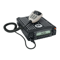
APX 8500
Motorola APX 8500 Installation Manual
5
of 1
of 1 rating
95 pages
Give review
Manual
Specs
To Next Page
To Next Page
Loading...
-i
Pa
g
e
APX™ TWO-WAY RADIOS
APX 8500 MOBILE
RADIO
INS
T
A
L
L
A
T
ION
M
A
NUA
L
Draft
2
Table of Contents
Foreword
3
Parts Ordering
3
Computer Software Copyrights
3
Document Copyrights
3
Disclaimer
3
Trademarks
3
Installation Requirements for Compliance with Radio Frequency (RF) Energy Exposure Safety Standards
4
Table of Contents
5
Mobile Radio Model Numbering Scheme
15
Commercial Warranty
17
Limited Warranty
17
Motorola Solutions Communication Products
17
What this Warranty Covers and for How Long
17
General Provisions
18
State Law Rights
18
How to Get Warranty Service
18
What this Warranty Does Not Cover
18
Patent and Software Provisions
19
Governing Law
19
Chapter 1 Introduction
21
Mobile Radio Description
21
Dimensions
21
MID Power Dash Mount Transceiver and Trunnion
21
Figure 1-3. Front View of O3 Control Head with Coiled Cable
22
Figure 1-4. Side View of O3 Control Head with Coiled Cable
22
Figure 1-5. Front View of O5 Control Head Attached to APX 8500 MID Power Dash Mount Transceiver and Trunnion
22
Figure 1-6. Side View of O5 Control Head Attached to APX 8500 MID Power
22
Dash Mount Transceiver and Trunnion
22
Figure 1-7. Front View of O7 Control Head Attached to APX 8500 MID Power Dash Mount Transceiver
22
And Trunnion
22
Figure 1-8. Side View of O7 Control Head Attached to APX 8500 MID Power Dash Mount Transceiver and Trunnion
22
Figure 1-9. Front View of Remote Mount and Trunnion
22
Figure 1-10. Side View of Remote Mount and Trunnion
22
Figure 1-11. Front View of O2 Control Head with Remote Mount and Trunnion
23
Figure 1-12. Side View of O2 Control Head with Remote Mount and Trunnion
23
Figure 1-13. Front View of O5 Control Head with Remote Mount and Trunnion
23
Figure 1-14. Side View of O5 Control Head with Remote Mount and Trunnion
23
Figure 1-15. Front View of O7 Control Head with Remote Mount and Trunnion
23
Figure 1-16. Side View of O7 Control Head with Remote Mount and Trunnion
23
Figure 1-17. Front View of O9 Control Head with Trunnion
24
Figure 1-18. Side View of O9 Control Head with Trunnion
24
Figure 1-19. Top View of O9 Universal Relay Controller with Trunnion (URC Is an Orderable Accessory)
24
Figure 1-20. Side View of O9 Universalrelay Controller with Trunnion(URC Is an Orderable Accessory)
24
Figure 1-21. Siren and Lights Interface Module (SLIM)
24
Figure 1-22. Front View of SB9600 Whelen Siren
25
Figure 1-23. Siren/Pa Cable Connections
25
Standard Configurations
26
Dash Mount Configuration
26
Figure 1-24. Dash Mount Configuration for O2 Control Head
26
Figure 1-25. Dash Mount Configuration for O3 Control Head
26
Figure 1-26. Dash Mount Configuration for O5 Control Head
27
Figure 1-27. Dash Mount Configuration for O7 Control Head
27
Remote Mount Configuration
28
Figure 1-28. Remote Mount Configuration with MID Power Transceiver, Transceiver Interface Board, CHIB Rear Assembly and O2 Control Head
28
Figure 1-30. Remote Mount Configuration with MID Power Transceiver, Transceiver Interface Board
29
CHIB Rear Assembly and O5 Control Head
30
O7 Control Head
31
Multi Control Head
35
Motorcycle Configurations
35
Base/Control Stations
35
Tools Required for APX Mobile Installations
35
Chapter 2 Standard Configurations
37
Planning the Installation
37
O9 Control Head
38
Radio Operation Wiring for Dash and Remote Configurations
51
Dash Mount: Power, Ignition, and Emergency Cable Installation
51
External Speaker
51
Remote Mount: Power, Ignition, and Emergency Cable Installation
52
Table 2-1. Dash and Remote O2, O3, O5, O7 or O9 Radio Power on @ J2
53
Table 2-2. Remote O2, O5, O7 or O9 Radio Power on @ J200
53
Table 2-3. Ignition Interface Cables
53
Ignition Sense Switch (Radio Wide Advance)
54
Table 2-4. Ignition Sense Switch Settings in CPS
54
Motorola Branded SB9600 Siren/Pa Configuration/Programming
56
Table 2-5. Power Level Configurations
56
Radio Mounting
57
Table 2-6. MID Power Trunnion Kit
59
Remote Mount with Trunnion
61
Remote Mount Control Head Installation
62
Multiple Control Head Installation
65
Table 2-7. Available CAN Cables
68
Cable Installation
69
Setting the Initial Control Head ID
69
O3 Control Head and Remote Mount Cabling
70
Locking Kit (Optional)
72
All Radios
72
Power Cables (Transceiver and Control Head)
73
O2, O5, O7 or O9 Control Head Power Cables
73
Table 2-8. Power Cables
73
Battery Selector Switch
74
Antenna Installation
75
Selecting an Antenna Site/Location on a Metal Body Vehicle
75
Multiplexers and Vehicle Installation
77
QMA Connection (APX8500 Only)
77
Gps/Glonass/Wi-Fi/Antenna Placement (APX8500 Only)
77
Speaker
78
Internal Speaker Disassembly
79
Microphone Hang-Up Clip
82
Standard or O3 Control Head Hang-Up Clip
82
RFID (Option)
82
RFID Reading
83
Programming RFID (if Equipped)
86
Table 2-1. Model Number Chart in 12-Digit ASCII Format
86
Table 2-2. Serial Number with Radio Band/Tier/Power
86
Completing the Installation
87
Chapter 3 Universal Relay Controller Installation
89
Universal Relay Controller Mounting
89
Figure 3-2. Universal Relay Controller Installation Exploded View
90
O7/O9 Universal Relay Controller Cable Assembly
91
Power Cable
91
Ground Cable
91
Wires
92
O7/O9 to URC Cable
93
Chapter 4 Options and Accessories Installation
95
Dash-Mount Accessory Installation
95
Dash-Mount Emergency Pushbutton or Footswitch Installation
95
Emergency Pushbutton or Footswitch Installation
95
Other manuals for Motorola APX 8500
Manual
273 pages
5
Based on 1 rating
Ask a question
Give review
Questions and Answers:
Need help?
Do you have a question about the Motorola APX 8500 and is the answer not in the manual?
Ask a question
Motorola APX 8500 Specifications
General
GPS
Yes
Bluetooth
Yes
Frequency Bands
VHF, UHF, 700/800 MHz
Encryption
DES
Wi-Fi
Yes
Technology
P25
Operating Temperature
-30°C to +60°C
Related product manuals
Motorola APX 8000
161 pages
Motorola APX 8000H
146 pages
Motorola APX 8000 3
202 pages
Motorola APX 8000XE
108 pages
Motorola APX 8000XE 1
121 pages
Motorola APX 8000XE 1.5
93 pages
Motorola APX 1000
166 pages
Motorola APX 7500
70 pages
Motorola APX 6500
52 pages
Motorola APX 6000
200 pages
Motorola APX NEXT
119 pages
Motorola APX Series
128 pages