6. Rotate the unit to the preplanned mounting angle and
t
ighten the two threaded knobs holding the charger to
the bracket.
7. Referring to Table 1 on page 2 and Figure 2, connect
the red (A+) wire (with the inline fuse) of the supplied
cable to either an unswitched terminal on the fuse box
of the vehicle or directly to the positive (+) terminal of
the battery of the vehicle. Always position the fuse as
close to the voltage source as possible.
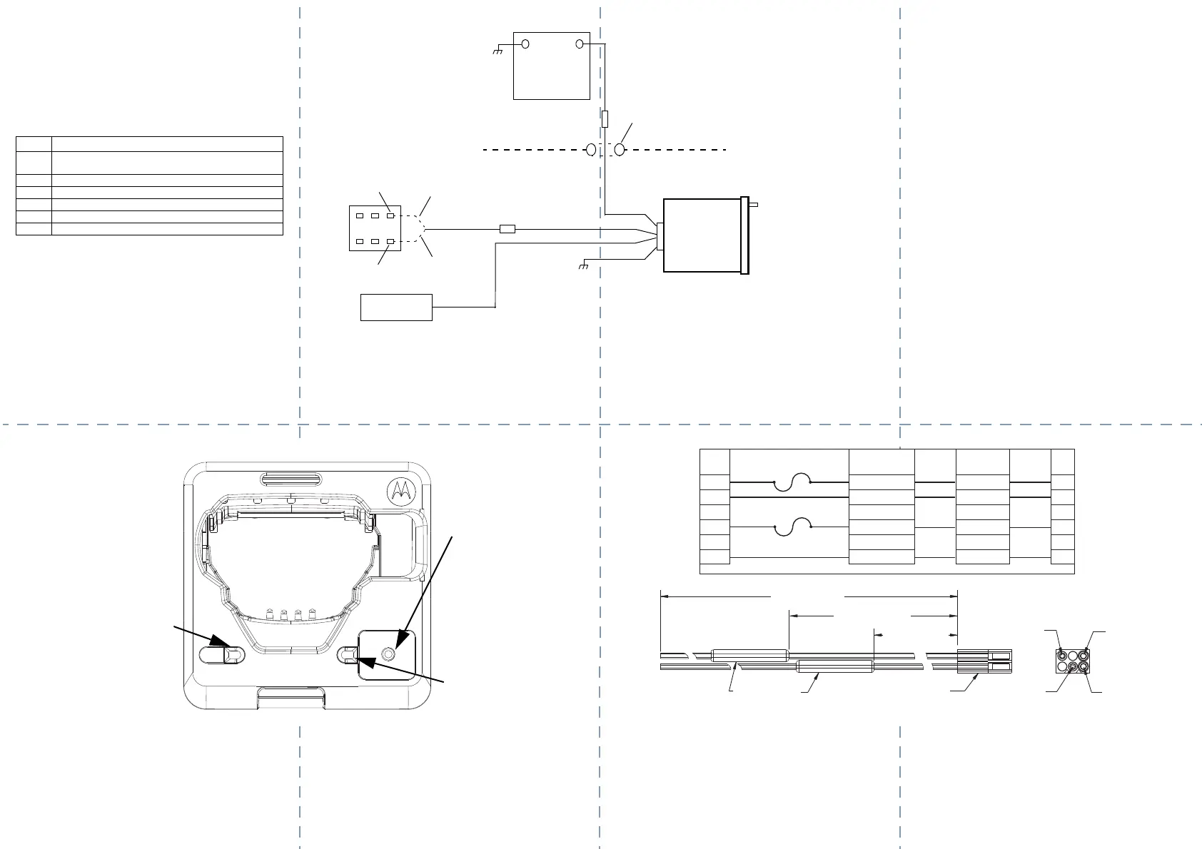
Table 1: Cable Connector Pins
Pin Connected To
1
Positive (+) vehicle battery terminal or unswitched fuse
terminal
2 Repeater (Vehicle Repeater System)
3 Not connected
4 Switched fuse terminal (ignition sense)
5 Not connected
6 Vehicle ground
Figure 2 Cable Console
5-AMP
INLI
NE FUSE
OPTIONAL
CHASSIS
VEHICLE
BLACK
13.8- or 27-VOLT
VEHICLE
BATTERY
+
_
GROMMET
FIREWALL
RED
YELLOW
WHITE
REPEATER
BOX
FUSE
VEHICLE
CHARGER
0.25-AMP
INLINE FUSE
OPTIONAL
STANDARD
A+
SWITCHED A+
8. There are two methods for Step 8:
• Standard wiring to vehicle Switched A+: Charging
OFF with vehicle OFF. For installations where the
radio may be left in the charger with the ignition of the
vehicle switched OFF and minimal vehicle battery cur-
rent drain is important, the standard wiring connection
of the yellow wire to vehicle switched A+ will disable
charging. Connect the yellow (ignition sense) wire (with
the inline fuse) to a switched terminal on the fuse box of
the vehicle. It is important not to connect the yellow wire
to the red lead.
• Note: The charger will remain ON for approximately 30
minutes after ignition is turned OFF.
• Optional wiring to vehicle A+: Charging ON with
vehicle OFF When the radio is left in the charger for
charging with the ignition of the vehicle switched off, the
optional wiring connection of the yellow wire to always
live vehicle A+ will keep the charger ON. The charger, in
this condition will not power down and will continue to
drain the vehicle battery.
9. Connect the black (ground) wire to any convenient vehi-
cle ground. DO NOT connect the black wire directly to
the vehicle battery negative terminal.
10. The white wire is for vehicle repeater operation only.
Please refer to installation instructions of the vehicle
repeater for instructions on the connection of this wire.
Figure 3 Top View of the Vehicle Charger
11. Recheck all wiring connections, cable routing, and all physical aspects of the installation. Carefully insert the connector on the
en
d of the cable into the mating connector on the back of the charger and test the charger for proper operation. Note that if a
vehicle repeater is installed, verify operation of the repeater before leaving the vicinity of the vehicle.
VRS
Status LED
Charger Status
LED
VRS Status Toggle -
Allows the user to
enable the repeater
when no radio is
present.
Figure 4 Cable Wiring Diagram
AWG
18
18
Signal
A +
5HSHDWHU956
Ignition Sense
Gnd
Color
Red
White
Yellow
Black
1
2
3
4
5
6
Pin
No.
Fuse A 25V
Fuse .5A 2509
Connector P-1Connector P-1
16”(406 mm)
36”(914 mm)
Fuse Holder
Inline Type
Connector P1
Molex P/N: 03-09-1064
Pin 4
Pin 2
Pin 1
Pin 6
21” (533 mm)
MN009444A01-AB.fm Page 2 Sunday, August 21, 2022 10:21 AM

 Loading...


