Do you have a question about the Motorola DIMETRA MTS 2 and is the answer not in the manual?
Provides an overview of the MTS, its functions, and interfaces within the Dimetra IP system.
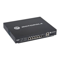
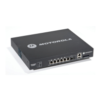
Details the components comprising the MTS 2 cabinet, including steel cabinet, front door, junction panel, filter section, and internal modules.
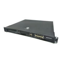
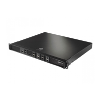
Details the components comprising the MTS 4 cabinet, including steel cabinet, front door, junction panel, filter section, and combiner section.
Describes the components of the Expansion Cabinet, including steel cabinet, junction panel, filter section, combiner section, card cages, and internal modules.
Provides an overview of available MTS modules and their subcomponents, covering RF Distribution System, Preselector, Duplexer, Post Filter, Cavity Combiners, Hybrid Combiner, and Rx Splitter.
Summarizes safety information for understanding and observing when working with Motorola TETRA Stations (MTSs).
Provides safety information specifically related to mains safety when working with or operating MTSs, highlighting hazardous mains voltages.
Details safety information specific to working with or operating MTS batteries, including precautions for Lithium batteries and harmful gases.
Explains the importance of proper planning to prevent interference and maximize system performance, emphasizing site layouts and minimizing cabling lengths.
Details the process of inspecting and surveying a site using appropriate forms before placing equipment orders, including key items to include.
Provides recommendations for site selection, including access clearance, ceiling structure for cable trays, room door dimensions, operating temperatures, and mains outlet availability.
Covers cabinet considerations, including dimensions and minimal distances for installation, noting that cabinets are not approved for outdoor use.
Describes considerations for antenna installation, including RF antenna, GPS antenna, and surge arrestors.
Details environmental factors affecting MTS operation, including temperature, humidity, corrosive environments, and air quality.
Outlines electrical wiring requirements, emphasizing adherence to local codes and regulations, and reinforced insulation for hazardous voltages.
Specifies grounding methods and standards for adequate protection from lightning induced transients, emphasizing single-point ground method.
Explains the two ways MTS cabinets can be mounted: directly to the floor or using a mounting plate.
Identifies the typical personnel required for MTS site installation, including installation supervisor, installers, and commissioning engineer.
Details the procedure for inspecting MTS equipment upon unpacking, checking against the packing list, and reporting any damage or missing items.
Ensures best possible performance and reliability by detailing required pre-installation planning and activities.
Provides recommendations for moving and locating equipment to the final position, suggesting specialized transportation companies.
Highlights crush hazards and recommends appropriate lifting apparatus, personnel, and compliance with regulations for moving cabinets.
Provides procedures for mounting the MTS cabinet within a site, emphasizing required clearances and securing the cabinet to the floor for stability.
Details the process of making electrical connections after mechanical installation, covering grounding, power supply, antenna, and GPS cables.
Explains how cabling from the equipment cabinet to external equipment is made through the MTS Junction Panel.
Outlines the required power supply connections for the MTS, including DC in/out and AC in options.
Provides a quick reference for installing the Low Voltage Disconnect (LVD) Kit for MTS2 and MTS4.
Describes the placement of RF antenna connectors on the junction panel for MTS 2 and the top of the cabinet for MTS 4.
Explains TX connection configurations between MTS 4 Prime Cabinet and MTS 4 Expansion Cabinet.
Illustrates how Site Controllers are connected to XHUBs, including connections for redundant Site Controllers.
Details CAN Bus cabling between MTS 4 Prime Cabinet and MTS 4 Expansion Cabinet, and for MTS 2.
Explains RX connection between MTS 4 Prime Cabinet and Expansion Cabinet, dependent on diversity.
Describes the integrated GPS module and the option for a remote GPS module for MTS Site Controller.
Explains the two modes of operation for adjacent cells: Synchronized and Non-Synchronized relative to the serving cell.
Details criteria for system initialization, focusing on Position Dilution Of Position (PDOP) and satellite tracking.
Describes the time taken for GPS startup, from applying power until the GPS LED is solid green.
Explains the placement of remote GPS antenna connectors of DB15 type on the junction panel.
Provides requirements for remote GPS receiver antenna mounting and isolation from RF interference.
Details the connection of the remote GPS receiver using standardized cables and surge protectors.
Describes cabling between the network termination unit (NTU) and the E1/X.21 interface on the MTS Junction Panel.
Explains how to gain Ethernet site link functionality using breakouts or a retrofit kit on MTS Junction Panels.
Details the alarm inputs and control outputs available on the junction panel for MTS 2 and MTS 4.
Consists of final check-out setup and Expansion Cabinet power-up procedures to ensure proper MTS operation.
Lists recommended tools, test equipment, and locally procured parts required for installation.
Describes AC and DC power cabling between the Junction Panel, Power Supply Unit, and other modules within the cabinet.
Details cabling between the Site Controller and connectors on the Junction Panel for User Alarms/Controls, X.21, RGPS, and GPS.
Explains E1 cabling between Site Controller and Junction Panel, and Ethernet cabling between Site Controller and Base Radios.
Describes Ethernet Site Link cabling for MTS Junction Panels, including retrofit kits and configurations.
Covers cable connections among antenna connectors, RFDS, and Base Radios, depending on filter configuration.
Details CAN Bus cabling, integrated in the Site Controller, connecting Site Controllers, PSUs, DPMs, and ATCCs.
Identifies and shows CAN Bus cabling for MTS 2 with TX/RX on 1 ant. and RX on 2 ant., and TX/RX on 2 ant. RX on 1 ant.
Details CAN Bus cabling for MTS 4 with TX/RX or TX on 1 ant. with ATCCs, and TX/RX or TX on 2 ant. with ATCCs.
Lists the CAN Bus Cabling for MTS 4 with Expansion Cabinet, detailing connections between Prime Cabinet and Expansion Cabinet.
Explains how setup and test procedures are used to test MTS functionality and isolate failures to the module level.
Details preparation steps before proceeding with configuration and testing, including MMI commands, test equipment, and service terminal setup.
Describes the usage of Man-Machine Interface (MMI) commands and MTS modes of operation for Site Controller and Base Radio.
Lists recommended test equipment for Equipment Cabinet procedures, emphasizing the need for ground system connection.
Explains the function and pinout of the Basic Service Cable and Service Connector Box for connecting to Site Controller or Base Radio.
Provides instructions for configuring the service terminal's RS-232 port and connecting it to the Site Controller's service port.
Explains CAN Bus interconnectivity for signaling, configuration, and troubleshooting, detailing commands for PSU, Fans, DPM, and ATCC.
Specifies steps to verify operation within the Site Controller, including setup, E1/X.21 connection tests, and site reference checks.
Details procedures to ensure Base Radio is up and running, covering startup sequence, position selection, receiver configuration, and station verification.
Verifies transmitter operation and integrity of the transmit path for the Power Amplifier.
Sends a known test signal to the Base Radio to verify the receive path, recommended after replacing a Base Radio.
Recommends synchronizing NVM regions after major changes to settings, using specific commands to copy working region to default region.
Explains how the RFDS module distributes and manages network frequencies, mitigating interference for improved radio reception.
Details the RFDS components for MTS 2, including Preselectors, Duplexers, Hybrid Combiners, and Filter Tray.
Describes the high-power RFDS for MTS 4, including Preselectors, Post Filters, Duplexers, Hybrid Combiners, and Cavity Combiners.
Details the RFDS for the Expansion Cabinet, including RX Splitters and Cavity Combiners, supporting up to four Base Radios.
Explains the RX Splitter as a passive device extending the Receiver Multi Coupler function for MTS 4 to support eight Base Radios.
Outlines tasks for replacing the Expansion Cabinet RX Splitter, referencing relevant procedures for removal and reinstallation.
Explains how the Site Controller manages resources, including frequency and slot assignment, and its GPS module for timing signals.
Details the front panel indicators (LEDs), switches, and connectors, as well as rear panel connectors for the Site Controller.
Describes the purpose and functionality of the CAN Bus for communication between RFDS equipment, PSU, and Site Controller.
Provides procedures for updating the CAN Bus unit mapping list after replacing a unit, using MMI commands.
Explains the GPS module's function for timing reference signals and its connection to the Site Controller.
Details procedures for checking and replacing the Site Controller's lithium battery, including safety precautions.
Covers procedures for restoring MTS operation, including disabling firewalls and understanding modes of operation.
Outlines the process for replacing a Site Controller FRU, including checking restoration impact and configuration backup.
Explains how to configure E1 links between MTS and CNE core router using MMI commands.
Details parameters required for Ethernet Site Link setup for Base Station, including WAN, VLAN, and IP tunnel configurations.
Explains the XHUB Controller as a non-intelligent switching and interface module for MTS 4 Expansion Cabinets.
Details the front and rear panel indicators, switches, and connectors for the XHUB Controller.
Describes the front panel layout, including indicators (LEDs), switches, and connectors of the XHUB Controller.
Provides procedures for replacing the XHUB Controller FRU, including safety precautions and steps for removal and installation.
Provides an overview of the Base Radio, highlighting its digital radio capabilities, channel capacity, and front panel components.
Explains the Base Radio's digital communications capabilities, subcomponents (Transceiver, PA), and operation with Site Controller.
Details the Base Radio's front panel LEDs for status monitoring and connectors for various interfaces.
Outlines the procedure for replacing a Base Radio module, including electrostatic discharge precautions.
Describes procedures for removing and reinstalling a Base Radio module, including power down and cable management.
Explains the PSU's function, AC/DC inputs, DC output voltages, and operating modes, including battery charging.
Details how the PSU is monitored and controlled by the Site Controller via CAN Bus, covering parameters, alarms, and controls.
Describes the PSU's fan supply outputs, voltage, current, and regulation, along with control via CAN Bus.
Lists and describes PSU indicators (LEDs), switches, and connectors on the PSU front panel.
Outlines the steps for replacing a PSU module, including PSU removal and PSU installation procedures.
Provides procedures for updating the PSU TrackID mapping list with the new PSU TrackID.
Explains that fan modules manage cabinet temperature, with revolution monitoring and alarm generation on failure.
Describes how fan kits reside below modules and are controlled by PSU with variable speed, based on module temperature.
Details fan supply outputs, specifications, and MMI commands for controlling fan voltage and speed.
Lists alarms and controls available through the CAN Bus for fans, including fan status and prevention of alarms.
Describes the airflow path for MTS 2 and MTS 4 cabinets, highlighting obstructions and the requirement for fans in MTS 4.
Explains cooling methods, including natural convection for MTS 2 and forced air from fans for MTS 4 configurations.
Provides procedures for replacing the MTS Fan Kit, including opening the housing, unplugging the connector, and securing the new kit.
Covers troubleshooting using Site Controller and Base Radio LEDs, MMI status, and fault indications.
Lists possible Site Controller failures with corresponding corrective actions, recommending module replacement for isolated failures.
Provides a flowchart to guide troubleshooting steps, starting from checking power and LEDs to verifying MMI availability.
Details troubleshooting steps for power issues, including checking power supply unit failure and verifying power connections.
Explains usage of the MMI command 'status sc' for general troubleshooting and determining Site Controller status.
Emphasizes the need for a valid configuration file for SC operation and describes how to check its validity.
Details usage of the MMI command 'status bts' for general troubleshooting and determining BTS subsystem status.
Highlights the necessity of valid configuration and code files for BRC operation and how to ensure their validity.
Describes how to check file validity in the Flash Filing System using 'ls' and 'attrib' commands.
Divides fault condition diagnosis into GPS/site reference and site link, providing example outputs for status commands.
Details troubleshooting for GPS and Site Reference faults, explaining different states and their implications.
Provides detailed information on GPS receiver operating state and satellite tracking reports, including troubleshooting steps.
Explains initial verification of IP pathway to Core Routers using ping MMI command and checking Frame Relay fragmentation.
Addresses issues with no uplink or downlink audio, suggesting checks for UDP port configuration and CRTP activity.
Consists of checking correct operation of each layer, starting with the physical layer, and verifying Site Link state.
Details how to check the state of the E1 interface using front panel LEDs and MMI commands.
Explains how to determine the state of the E1 interface by inspecting front panel LEDs and using MMI commands.
Lists common Site Controller symptoms, possible failures, and corrective actions for issues like initial power up failures.
Covers troubleshooting for Base Radio, RFDS, and miscellaneous issues using LEDs, MMI status, and fault indications.
Provides a guide to isolate Base Radio failures to the module level, containing troubleshooting and verification procedures.
Serves as a guide to isolate Base Radio failures to the module level, including procedures for troubleshooting and verification.
Presents Environmental Specifications and Standards Specifications for MTS equipment.
Details operating temperature, storage temperature, humidity, and operational altitude specifications.
Lists relevant standards for TETRA, Air-Interface, Conformance Test, EU Directives, Digital Line Interfaces, and Safety.
Contains dimensions for MTS 2, MTS 4, and MTS 4 Expansion Cabinets, and technical specifications for various modules.
Provides RF specifications including frequency bands, bandwidth, channel spacing, and maximum transmit power.
Lists transmit specifications for TETRA and TEDS, including power, modulation accuracy, and adjacent-channel power.
Provides receiver specifications for TETRA and TEDS, including sensitivity, degradation, and interference levels.
Describes how MTS 2 is complemented with an additional Base Radio, including list of equipment and installation process.
Details how to add an additional module cage to an MTS 4 cabinet, including list of expansion kit equipment and installation procedure.
Describes how to add a Base Radio into an existing module cage of the MTS 4, including configuration parameters.
Describes how to add a redundant Site Controller to MTS 4, including required hardware and software releases.
Explains how to expand from a two-channel Cavity Combiner to a four-channel Cavity Combiner for MTS 4.
Describes how to expand the Hybrid Combiner for MTS 4, including list of equipment and installation procedure.
Details how to expand from an existing MTS 2 to MTS 4, including extraction and assembly of Module Cage.
Describes how to add a redundant XHUB Controller to an MTS 4 Expansion Cabinet, requiring a redundant Site Controller.
Describes the MTS 4 outdoor enclosure's design for withstanding rough environments and years of service.
Lists available Field Replaceable Units (FRUs) for MTS 2, including Site Controller, Base Radios, Power Supply Unit, and GPS accessories.
Lists available FRUs for MTS 4, including Site Controller, Base Radios, Power Supply Unit, Hybrid Combiners, Duplexers, Post Filters, and Preselectors.
Details three types of surge arrestors for MTS sites: AC Power/E1/X.21, Antenna, and Lightning, with supplier addresses.
Recommends antenna surge arrestors manufactured by Polyphaser, Inc., listing recommended models for various applications.
Provides information on available Lightning Arrestors from a European supplier, HOFI GmbH & Co KG.
Lists planned maintenance requirements for MTS 2 modules, indicating when PMI action is required or recommended.
Details Planned Maintenance Inspection (PMI) requirements for Duplexer Digital Power Monitor modules.
Lists Planned Maintenance Inspection (PMI) requirements for Preselector modules.
Lists planned maintenance requirements for MTS 4 modules, indicating PMI requirements for Site Controller and Base Radios.
Lists other replaceable parts and accessories for MTS 4 PMIs, indicating whether misalignment will be detected in general station tests.
Emphasizes the use of a static grounding wrist strap when handling MTS boards or modules, and precautions against static build-up.
Explains the purpose of the ESD socket and the use of an ESD wrist strap and earthing point for protection.