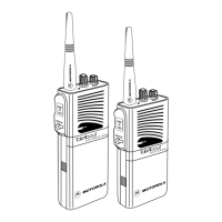
1-2 Introduction: Radio Description
1.2.1 Non Keypad Model
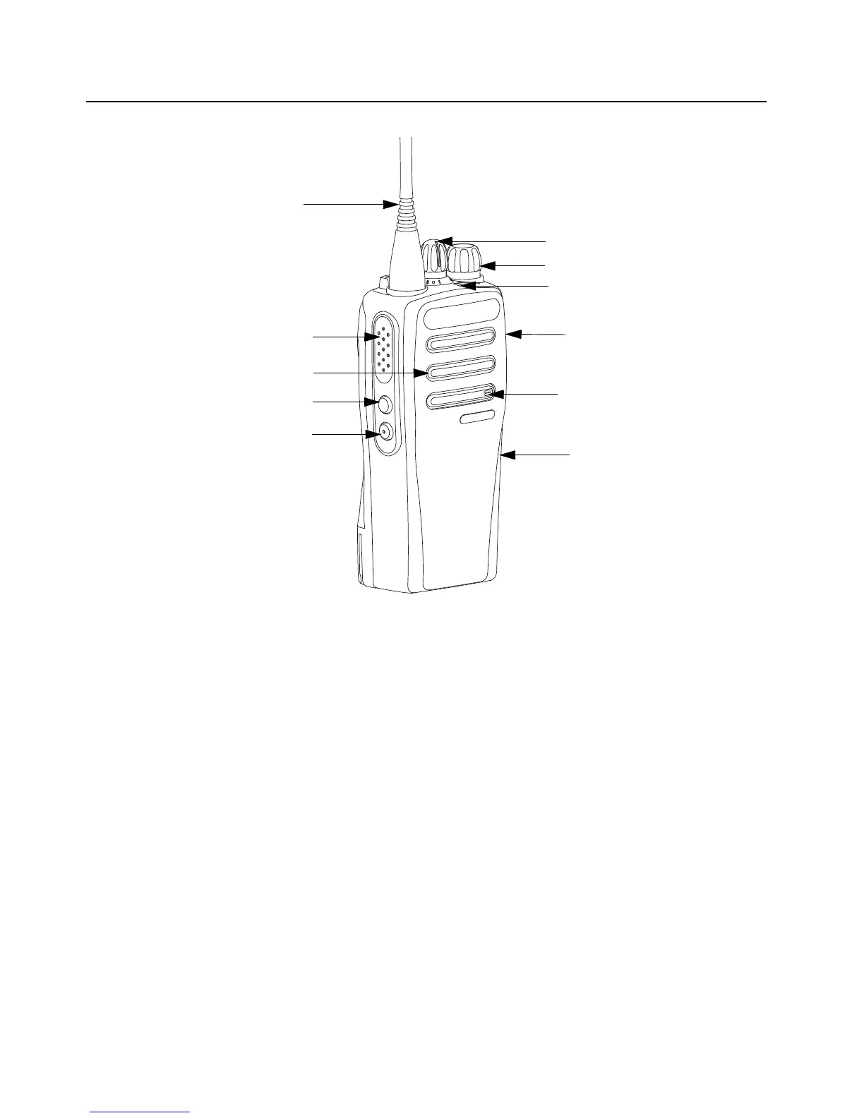
Figure 1-1. Non Keypad Model
• ON/OFF/VOLUME KNOB – Rotate clockwise until click is heard to turn on radio; rotate counter-
clockwise until click is heard to turn off radio. Rotate clockwise to increase volume level; rotate
counter-clockwise to decrease volume level.
• LED INDICATOR – Red, green and orange light-emitting diodes indicate operating status.
• SIDE BUTTONS – These 2 buttons are field programmable using the CPS.
• CHANNEL SELECTOR KNOB – Rotate clockwise to increment and counter clockwise to
decrement the channel.
• PUSH-TO-TALK (PTT) – Press to execute voice operations (e.g. Group call and Private Call).
• ANTENNA – Provides the needed RF amplification when transmitting or receiving.
• MICROPHONE – Allows the voice to be sent when PTT or voice operations are activated.
• ACCESSORY CONNECTOR WITH DUST COVER – Interface point for all accessories to be
used with the radio. It has eight points to which specific accessories will connect to and be
activated.
• SPEAKER – Outputs all tones and audio that are generated by the radio (e.g. features like
keypad tones and voice audio).
• USB WITH DUST COVER – Dust cover to prevent dust from clogging USB port.
Antenna
Channel Selector Knob
On/Off Volume Control Knob
Push-to-Talk (PTT) Button
Side Button 2 (Programmable)
LED Indicator
Speaker
Microphone
USB with Dust Cover
Side Button 1 (Programmable)
Accesory Connector
with Dust Cover
 Loading...