Do you have a question about the Motorola DP1400 Series and is the answer not in the manual?
Explains the use of note and caution notations for safety and emphasis.
Details the frequency ranges and power levels of the DP1400 radios.
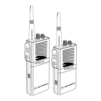
Identifies and describes the physical components of the non-keypad model.
Explains the structure and meaning of the radio's model number.
Provides charts listing different VHF model variants and their descriptions.
Lists various UHF model variants and their corresponding descriptions.
Details the general and technical specifications for the DP1400 radios.
Lists essential test equipment required for servicing Motorola portable radios.
Details specific service aids and their applications for radio maintenance.
Describes the portable programming cable and its connection details.
Describes the portable test cable and its pin configuration for testing.
Provides an overview of transceiver performance testing methodology.
Details the necessary setup and equipment for alignment procedures.
Explains how to enter and operate the radio in RF Test Mode for testing.
Outlines various test modes available on the radio for diagnostics.
Step-by-step instructions on how to activate the radio's test mode.
Details the operations and controls within the RF Test Mode.
Procedure for testing the radio's LED indicators.
Procedure for testing the radio's internal speaker tone output.
Procedure for testing the radio's earpiece tone output.
Procedure for testing audio routing to the earpiece.
Procedure for checking the radio's battery status indication.
Procedure for testing all radio buttons, knobs, and PTT switch.
Introduces Customer Programming Software (CPS) and related applications.
Instructions for setting up the Customer Programming Software.
Explains the functionality of the AirTracer tool for traffic analysis.
Outlines the equipment and PC setup for radio tuning procedures.
Provides an overview of maintenance, disassembly, and repair procedures.
Covers routine checks like inspection and cleaning for radio upkeep.
Details the process for visually inspecting the radio's external condition.
Specifies recommended agents and methods for cleaning radio surfaces.
Provides critical precautions for handling static-sensitive electronic components.
General guidelines and considerations for performing repairs on the radio.
Outlines general steps and required tools for disassembly and reassembly.
Step-by-step instructions for disassembling the radio components.
Detailed steps to separate the front cover from the radio chassis.
Procedure for separating the main chassis assembly from the front housing.
Steps for carefully sliding the chassis assembly out of the front housing.
Instructions for removing the audio jack shroud from the main board.
Steps to disconnect speaker and microphone wires from the main board.
Detailed procedure for removing the Generic Option Board (GOB).
Method for gently unlatching the connector actuator on the flex cable.
Steps to carefully remove the flex cable from its connector.
Procedure for lifting and removing the option board assembly.
Detailed steps for disassembling the main chassis and its components.
Instructions for removing the speaker and microphone assemblies.
Detailed steps for removing the audio jack dust cover.
Procedure for removing the audio jack dust cover using its key.
Detailed steps for removing the micro USB dust cover.
Procedure for cutting and removing the micro USB dust cover.
Step-by-step instructions for reassembling the radio components.
Detailed steps for reinstalling the micro USB dust cover.
Detailed steps for reinstalling the audio jack dust cover.
Instructions for reinstalling the speaker and microphone assemblies.
Detailed steps for reassembling the main chassis and its components.
Procedure for correctly placing the thermal pads on the chassis.
Steps to install the main PCB and top control seal.
Procedure for aligning and adhering the poron pad.
Detailed procedure for reassembling the Generic Option Board (GOB).
Step-by-step guide for folding the flex cable correctly.
Instructions for completing the reassembly of the option board.
Procedure for inserting the flex cable and closing the actuator.
Instructions for reassembling the chassis and front housing.
Procedure for reattaching the audio jack shroud assembly.
Steps for sliding the chassis assembly into the front housing.
Provides exploded views and part lists for radio components.
Exploded mechanical view and parts list for non-option board models.
Exploded mechanical view and parts list for option board capable models.
Lists torque specifications for various screws used in assembly.
Guidance on when to consider replacing circuit boards or seeking service.
Instructions for installing replacement back cover kits.
Outlines Motorola's support services, including warranty and post-warranty.
Provides contact details for the European Radio Support Centre.
Details how to contact support for resolving radio malfunctions.
Information on how to contact the Customer Help Desk and website.
Refers to specific sections for detailed maintenance procedures.
Instructions for replacing chip components using hot-air or soldering iron.
Lists components and their part numbers as shown on the PCB diagram.
| IP Rating | IP54 |
|---|---|
| Operating Temperature | -30°C to +60°C |
| Frequency Range | VHF (136-174 MHz); UHF (403-470 MHz) |
| Channel Capacity | 16 |
| Power Output | 5W (VHF), 4W (UHF) |
| Digital Protocol | DMR |