Accessory Connector 2-19
Each programmable pin can be disabled or programmed to a feature. The active state of each pin
can be set as high or low: except
emergency is active low;
ignition is active high.
Benefits
Enables interface to a wide range of external devices.
Customer specific applications can be catered for.
Gives excellent opportunities for enhanced dealer added value.
Interface to external Mobile Data Modems.
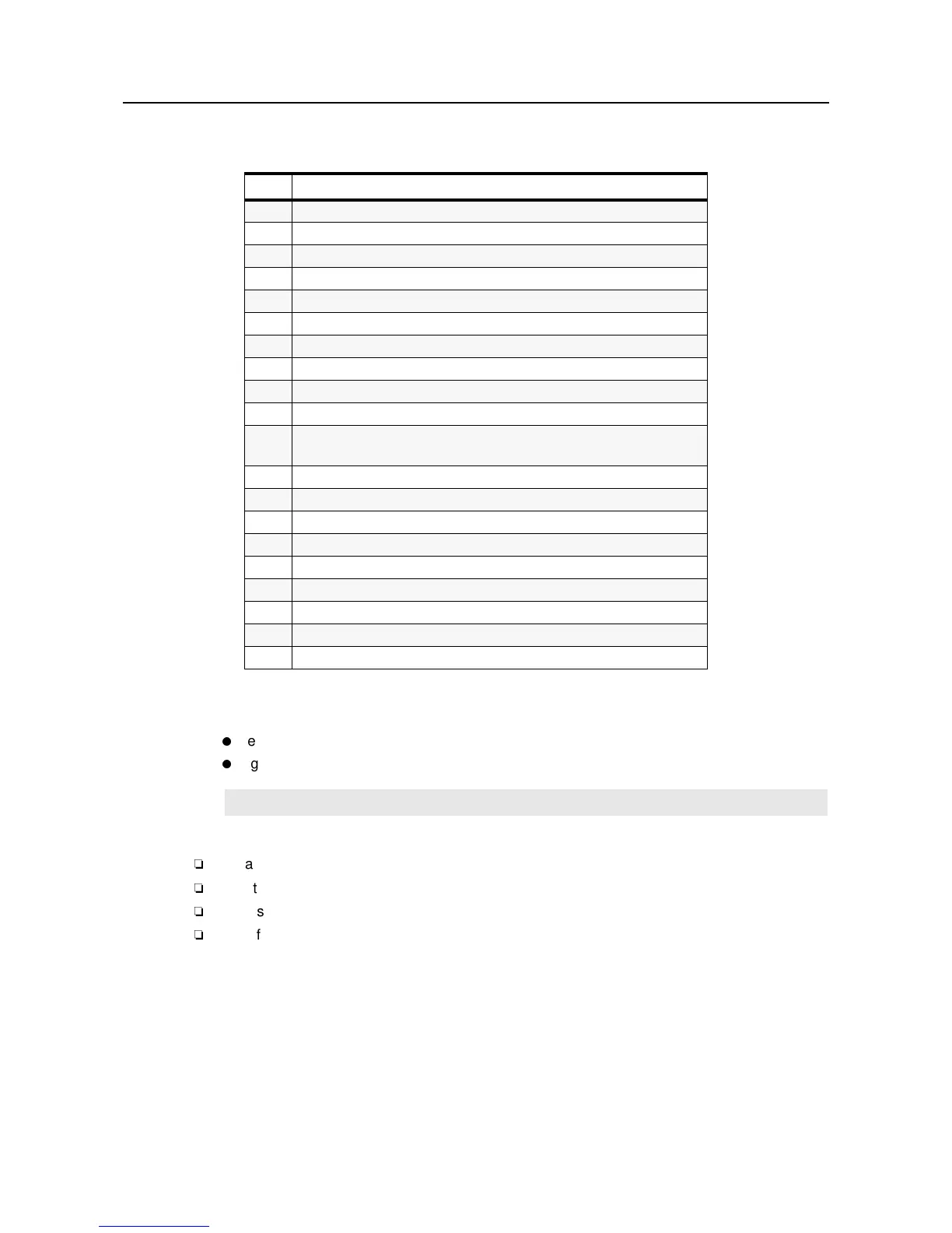
Table 2-4 Accessory Connector Pin Out
Pin
Function
1 Speaker -
2ExternalMic
3 Digital In 1 (Ext. PTT use External Mic/ Data PTT use Flat TX Audio)
4 Digital Out 2 (External Alarm)
5 Flat TX Audio. Sensitivity 150mV rms to for 60% deviation
6 Digital In 3
7 Ground
8 Digital In/Out 4
9 Digital In 5 with Wakeup (Emergency)
10 Digital In 6 with Wakeup (Ignition)
11 Flat / Filtered RX Audio (Flat RX Audio 330mV rms at 60% deviation
Filtered RX Audio 600mV rms at 60%dev at 1kHz) CPS selectable
12 Digital In/Out 7
13 Switched Battery Voltage (max 1A, Dropout Voltage max1V)
14 Digital In/Out 8
15 RSSI (Radio Signal Strength Indicator)
16 Speaker +
17 Bus+ (used for CPS and Flash)
18 Boot Control
19 Reserved
20 Reserved
NOTE
Please refer to the Radio Installation Manual for more information.

 Loading...