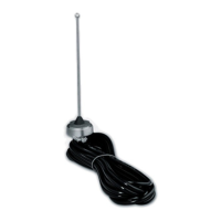
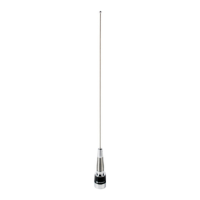
This document describes the installation and maintenance of Motorola Mobile Quarter-Wave Antennas, designed for both roof-mount and trunk-lip mount applications. These antennas are supplied with an antenna whip, coaxial cable, connector, and all necessary mounting hardware.
Function Description
The Motorola Mobile Quarter-Wave Antennas are designed to provide reliable radio frequency (RF) communication for mobile two-way radio systems. They are quarter-wave antennas, meaning their physical length is approximately one-quarter of the wavelength of the radio signal they are designed to transmit and receive. This design makes them efficient for mobile applications. The antennas are available in various models, each tuned to specific frequency ranges, ensuring optimal performance for different communication bands. The installation procedures are detailed for both roof-mount and trunk-lip mount configurations, catering to a wide range of vehicle types and user preferences. The document also provides critical information regarding antenna location to ensure both optimal radio performance and compliance with RF safety guidelines.
Important Technical Specifications
The antennas are categorized into roof-mount and trunk-lip mount models, each supporting different frequency ranges:
Roof Mount Models:
- HAD4006A: 136-144 MHz
- HAD4007A: 144-150.8 MHz
- HAD4008A: 150.8-162 MHz
- HAD4009A: 162-174 MHz
- HAE4003A: 450-470 MHz
- HAF4002A: 806-870 MHz
Trunk Lip Mount Models:
- HAD4010A: 136-144 MHz
- HAD4011A: 144-150.8 MHz
- HAD4012A: 150.8-162 MHz
- HAD4013A: 162-174 MHz
- HAE4007A: 449-470 MHz
- HAF4003A: 806-870 MHz
The roof-mount antennas are designed for installation on flat metal roofs with a thickness of 0.020 to 0.040 inches. The installation typically requires drilling a 3/8-inch pilot hole, followed by a 3/4-inch hole using a hole-cutting saw (Motorola part 01-80382A25 or equivalent). The coaxial cable supplied is 17-foot RG58A/U with a Mini UHF connector.
RF Safety and Antenna Location Guidelines:
For optimal radio performance and to ensure human exposure to RF electromagnetic energy is within guidelines, specific distances from the transmitting antenna are recommended based on the radio's rated power:
- 7 to 15 Watts: Minimum distance of 1 foot (30.5 cm)
- 16 to 50 Watts: Minimum distance of 2 feet (61 cm)
- More than 50 Watts: Minimum distance of 3 feet (91.5 cm)
Gutter mount antennas are not recommended for transmitters exceeding 6 watts.
Usage Features
Mounting Options:
- Roof Mount: Ideal for optimal radiation patterns, typically mounted in the center of the vehicle roof. This method ensures maximum signal coverage and minimizes interference.
- Trunk Lip Mount: Offers flexibility for installation on the top center lip of the trunk lid or to the side to prevent interference with the window. This option is suitable when roof mounting is not preferred or feasible.
Installation Flexibility:
The manual provides detailed installation procedures for various vehicle configurations:
- Single Wall Construction: A straightforward process involving drilling holes and securing the bushing assembly.
- Double Wall Construction (with or without dome lights/removable headlining): Specific steps are outlined to accommodate different roof structures, including cutting holes in inner metal layers and managing filler material.
- Vehicles Without Dome Lights: Instructions are provided for situations where headlining removal is not feasible, emphasizing careful hole cutting through both metal thicknesses.
Connector Installation:
The document includes a comprehensive guide for installing the Mini-UHF connector using specific Motorola hand tools (part #66-80388A26 or the deluxe ratchet type tool #66-80334B40). This ensures a secure and reliable connection.
Antenna Location Recommendations:
Motorola provides specific recommendations for antenna placement to optimize performance:
- Standard Metal Passenger Cars: Center roof or center trunk lid.
- Vans, Pickups, Light Trucks (metal roofs): Center roof.
- Heavy Duty Equipment (metal roofs, e.g., trucks, semi-tractors, cement mixers): Center cab roof.
- Specialty Vehicles (e.g., T-roofs, sun roofs, convertibles): Center trunk lid.
- General Rule: The best mounting location is the center of a large, flat conductive surface.
- Trunk Lid Mounting: Ensure the trunk lid is grounded to the vehicle chassis using grounding straps.
- Cable Routing: Antenna cable should be routed separately, not in parallel with other vehicle wiring or mobile radio cables, to prevent interference.
- Interference Check: Verify the antenna location for any electrical interference, especially from rubbing metal parts (seat springs, shift levers, trunk/hood lids, exhaust pipes).
- ABS Equipped Vehicles: If trunk-mounted, install the antenna on the side opposite to the braking modulator box to minimize radio interference.
- Minimum Separation: Maintain at least one foot (30.48 cm) separation from any other antenna on the vehicle.
Maintenance Features
Replacement Parts:
The manual lists various replacement installation hardware kits, both with and without the coupling kit, ensuring that users can easily obtain necessary components for repairs or reinstallation. These kits include:
- Silicone Grease (11-80369B40)
- Mini UHF Connector (28-84606M01)
- "O" Ring (42-83940B01)
- Locking Nut (43-83881B01)
- Coupling Nut (58-83882B01)
Frequency Conversion:
Antennas are equipped with whips cut to specific lengths for each frequency band. To change the operating frequency band, the whip assembly must be replaced with one of the appropriate length. For antennas in the 136-150.8 MHz range, a spring washer (part 4B83780C01 for roof mount models) is used for impedance matching. If changing from this range to another, the spring washer must be removed. Conversely, if changing to this range, the spring washer must be installed. This ensures proper impedance matching and optimal performance across different frequency bands.
Installation Best Practices:
- Burr Removal: After drilling holes, it is crucial to remove any burrs and foreign matter from the underside of the hole to ensure proper seating of the bushing assembly and good contact for the locking nut.
- Locking Nut Tightening: The locking nut must be tightened firmly until it bottoms against the roof top, ensuring the "O" ring is fully compressed. This contact is vital for the proper antenna radiation pattern. If the bushing assembly rotates during tightening, long-nose pliers or a spanner wrench can be used to hold it in place.
- Cable Protection: When routing the coaxial cable, especially in trunk-lip mount installations, ensure it is not pinched by the trunk lid or other vehicle components. Rubber grommets should be used in sheet metal holes to prevent cable damage.
Overall, the Motorola Mobile Quarter-Wave Antennas are designed for robust and flexible mobile communication, with detailed instructions to ensure correct installation, optimal performance, and adherence to safety standards.