Do you have a question about the Motorola IRRInet-M DC and is the answer not in the manual?
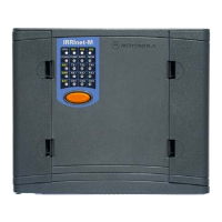
Provides a general overview of the IRRInet-M DC RTU, its features, and enclosure.
Details the unit's components including ports, modem, and I/Os.
Lists and describes the three communication ports available on the unit.
Details the various connectors on the IRRInet-M DC RTU and its expansion board.
Explains the function of the push-button and various LED indicators.
Describes how to control the LED display and perform specific functions like LED test.
Explains how to perform a CPU reset and interpret CPU fail error codes.
Details the LED matrix, page navigation, and general LED indications.
Describes the function of LEDs when the unit is in CPU mode.
Describes the function of LEDs when the unit is in IO1 page mode.
Describes the function of LEDs when the unit is in IO2 page mode.
Describes the function of LEDs when the unit is in IO3 page mode.
Describes the function of LEDs controlled by the user application.
Describes the function of LEDs during hardware testing.
Details the input/output capabilities of the unit and expansion board.
Lists the main components of the IRRInet-M RTU.
Explains the system architecture and communication methods of the IRRInet-M.
Provides essential safety warnings and guidelines for installing the unit.
Details the dimensions and space requirements for wall mounting the unit.
Provides step-by-step instructions for mounting the unit using screws.
Describes the procedure for mounting the unit on a DIN rail.
Illustrates and lists the ground connection points on the unit.
Details the power input requirements, fuse, and connection polarity.
Instructions for connecting an external radio to the unit.
Describes how to establish line communication between IRRInet-M units.
Covers specific installation procedures for external radios.
Covers opening/closing the case and antenna installation.
Explains how to configure the unit using the ACE3600 System Tools Suite (STS).
Details the default port configurations and how to change them.
Describes the default and expansion I/O configurations.
Explains how to configure advanced parameters for communication and I/Os.
Refers to the STS User Guide for hardware test configuration.
Introduces the appendix and the applications covered.
Details connections between the RTU and computers or terminals.
Describes how to connect the RTU to modems, including asynchronous connections.
Details how to connect external radios to the IRRInet-M.
Provides data on cables for RTU-to-RTU RS232/RS485 asynchronous interconnection.
Details cables for RTU-to-RTU line interconnection.
Introduces available models, options, and accessories.
Lists various options for the IRRInet-M, including radios and software.
Lists available accessories such as installation kits and adapters.
Lists the part numbers for various IRRInet-M components.
Details the installation kit for connecting specific radios to the IRRInet-M.
Shows how to connect specific radios to the IRRInet-M unit.
Provides steps to install a volume knob retainer on compatible radios.
Describes mounting radios and performing necessary wire connections.
Lists environmental operating conditions such as temperature and humidity.
Details the physical dimensions, weight, and connection types.
Specifies inputs, outputs, isolation, and LED functions for the basic board.
Specifies inputs, outputs, and isolation for the I/O expansion board.
Details specifications for various communication ports like RS232, Radio, and Line.
Details input voltage, auxiliary voltage, power consumption, and protection.
Lists the regulatory standards and safety certifications the product meets.
Introduces the chapter and lists included mounting kit parts.
Provides instructions for mounting the plastic box on a DIN rail.
Provides instructions for mounting the plastic box on a wall.
Details the procedure for detaching the plastic box and bracket.
| Category | Irrigation System |
|---|---|
| Manufacturer | Motorola |
| Model | IRRInet-M DC |
| Power Source | DC |
| Communication | Cellular |