2
English
Installation
1. The positive supply to the regulator should be taken from an
ignition switched source. This can be connected to the same
supply as used for ignition sense to DCK control box (green wire).
2. Connect coaxial cable end to 5 V input terminal on diplexor unit.
3. Run supply cable to selected connection point, ensuring that it is
secured from being damaged and does not interfere with any
vehicle controls or airbag deployment.
4. Connect grey regulator positive feed wire to ignition sense feed,
via 1 A fuse (using holder and connectors supplied).
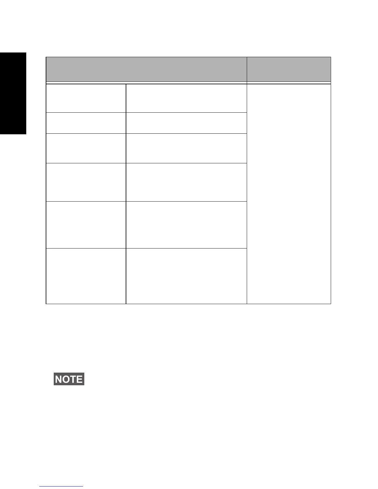
Table 1: FTN6790B Specifications
Specification Kit Content
Input Voltage
Range
7–30 V Regulator unit
moulded with
input and output
cables
1 x Fuseholder
1 x Fuse 1A rated
2 x Blade
connectors - red
insulated
Output Voltage 5 V
Max. Output
Current
40 mA
Dimensions
(regulator unit
block)
41 x 12.5 x 12.7 mm
Input cable Twin Figure-8
Length: 560 mm
Negative marked black
tracer line
Output cable RG174 Coaxial Cable
Length: 550 mm
Terminated FME Jack (f)
Centre contact positive
supply
The positive supply must be fused at maximum 1 A rating.

 Loading...


