Do you have a question about the Motorola XiR Series and is the answer not in the manual?
Controls the power state of the radio.
Adjusts the audio output volume.
Buttons P1, P3, and P4 can be programmed for specific functions.
Shows radio status, icons, and text.
Navigates through channels or menu options.
Outputs audio for calls and alerts.
Port for connecting external accessories.
Visual indicators for radio status.
Navigates left or right within menus.
Accesses or exits menus.
Confirms selections or actions.
Returns to the previous screen or home.
Shows radio signal strength with bars.
Indicates Low (L) or High (H) power setting.
Indicates if Option Board is enabled or disabled.
Shows GPS enabled status and position fix.
Indicates when scan feature is enabled.
Indicates unread messages, emergency mode, and privacy.
Indicates when the radio is searching for a site.
Indicates a private phone call in progress.
Shows if a text message was sent successfully or failed.
Describes red blinking patterns for alerts and self-tests.
Describes green and yellow LED patterns for various operations.
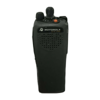
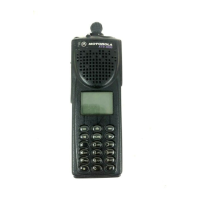
The Motorola XIR Series Digital Mobile Radios are designed for robust communication, offering a range of features for both individual and group interactions. This quick reference guide focuses on the display model, detailing its controls, display icons, LED indicators, and various operational procedures.
The device serves as a digital mobile radio, facilitating voice communication (private calls, group calls, site all calls, phone calls) and text messaging. It supports programmable buttons for quick access to frequently used functions and includes features like scanning talkgroups, emergency calls/alerts, and enhanced privacy. The radio is designed for use in systems where network sites may be restricted, and it can automatically search for allowed network sites.
While specific technical specifications like frequency ranges or power output are not detailed in this guide, the manual highlights several operational aspects:
The radio offers a comprehensive set of usage features:
The manual does not explicitly detail maintenance features but implies:
| Brand | Motorola |
|---|---|
| Model | XiR Series |
| Category | Portable Radio |
| Language | English |