EasyManua.ls Logo

Motostar LINESTAR User Manual

Motostar LINESTAR
24 pages
To Next Page IconTo Next Page
Page #1 background imageLoading...
Page #1 background image
AUTAUT
AUTAUT
AUT
OMAOMA
OMAOMA
OMA
TION FOR SLIDING GATION FOR SLIDING GA
TION FOR SLIDING GA
TESTES
TESTES
TES
INSTALLATION MANUAL
LINESTLINEST
LINESTLINEST
LINEST
ARAR
ARAR
AR
Question and Answer IconNeed help?

Do you have a question about the Motostar LINESTAR and is the answer not in the manual?

Motostar LINESTAR Specifications

General IconGeneral
BrandMotostar
ModelLINESTAR
CategoryGarage Door Opener
LanguageEnglish

Summary

1.0 STANDARD SYSTEM DESCRIPTION

1.1 DESCRIPTION OF THE GEARMOTOR UNIT COMPONENTS

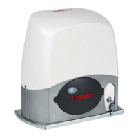
Details the components of the gearmotor unit assembly.

2.0 GENERAL CHARACTERISTICS

2.1 TECHNICAL CHARACTERISTICS OF THE GEARMOTOR

Provides detailed technical specifications for the 24V irreversible gearmotor.

2.2 DIMENSIONS OF THE AUTOMATION

Illustrates the physical dimensions of the gate automation system.

3.0 ASSEMBLY OF THE UNIT

INSPECTIONS OF THE GATE BEFORE INSTALLATION

Checks required for the sliding gate prior to commencing unit assembly.

PREPARING AND FIXING THE ANCHORING PLATE

Steps for preparing the ground cavity and fixing the anchoring plate.

FIXING THE CHAIN

Instructions for marking, drilling, and securing the gate chain.

LAYING THE UNIT

Procedure for positioning and securing the gearmotor unit onto the anchoring plate.

RELEASING THE GEARMOTOR AND ADJUSTING THE END-STOP UNIT

How to release the gearmotor and adjust the end-stop microswitches.

4.0 DESCRIPTION OF THE CONTROL BOARD

Control and safety logic

Explains the control unit's logic and how it handles obstacles.

4.1 MAIN COMPONENTS OF THE CONTROL BOARD

Identifies and lists all the main components and terminals on the control board.

4.2 ELECTRIC CONNECTIONS

GEARMOTOR, TRANSFORMAR, POWER SUPPLY AND LIMIT SWITCH

Diagrams showing wiring for gearmotor, transformer, power, and limit switches.

SIGNALLING AND LIGHTING DEVICES

Voltage signalling LED

Details on the function of voltage signalling LEDs on the control panel.

COMMAND DEVICES

Incorporated reception antenna for remote radio-control use

Description of the integrated antenna for remote radio control.

Pedestrian opening pushbutton

Information on the pushbutton for pedestrian passage or maintained action opening.

Pushbutton for «Commands»

Details on the pushbutton for gate opening and closing commands.

«Stop» pushbutton

Explanation of the stop pushbutton's function and its effect on automatic closing.

SAFETY DEVICES

Connecting photoelectric cells for re-opening during closure

Configuration for photoelectric cells to re-open the gate during closure.

Photoelectric cells for re-opening and partial stop

Setup for photoelectric cells enabling re-opening and partial stop functions.

Photoelectric cells and safety rib configurations

Advanced safety configurations with photoelectric cells and safety ribs.

4.3 CHECK TEST OF THE PHOTOELECTRIC CELLS OPERATION

4.4 RADIO CODE PROGRAMMING

Radiofrequency board insertion

Instructions for correctly inserting the radiofrequency board.

Code storage

Steps for storing radio codes on the control board.

Transmitters duplication

Guide on how to duplicate existing remote control transmitters.

4.5 FUNCTION SELECTIONS

4.6 ADJUSTMENTS

4.7 LED CONTROL FUNCTIONS

4.8 CONNECTION FOR THE EMERGENCY BATTERIES

5.0 MAINTENANCE