EasyManua.ls Logo

MOTOYAMA EA91A - User Manual

MOTOYAMA EA91A
31 pages
Print Icon
To Next Page IconTo Next Page
Loading...
INSTRUCTIONMANUAL
BulletinNo.MIE-B6104KBulletinNo.MIE-B6104K
ModelEA91AEA90A
PrintedinJapan
2013.07.05TKP
ModelsEA91AFlameproofTypeof
Explosion-protectedConstruction
ModelEA90AIntrinsicSafetyTypeof
Explosion-protectedConstruction
ELECTRO-PNEUMATIC
VALVEPOSITIONERS
ThisINSTRUCTIONMANUALissuppliedforinformationpurposeonlyandshould
notbeconsideredcertifiedmarketabilityandconformabilityofthisproduct.
□MOTOYAMAiscontinuouslyimprovingandupqradingitsproductdesign,specificationsand/or
dimensions,Informationincludedhereinissubjecttochangewithoutnotice.
■HeadOfficeandFactory
5-2,OhiraAzakameoka,Ohira-Mura,Kurokawa-gun,Miyagi-ken,981-3697Japan
TEL:+81-22-344-4511/FAX:+81-22-344-4533
■OverseasMarketing&SalesDept
5-2,OhiraAzakameoka,Ohira-Mura,Kurokawa-gun,Miyagi-ken,981-3697Japan
TEL:+81-22-344-4546/FAX:+81-22-208-5020

Questions and Answers

  • C
    Christopher PhillipsAug 5, 2025
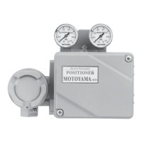
    What to do if MOTOYAMA Valve Positioners does not work normally?
    • K
      Kayla LopezAug 5, 2025
      If your MOTOYAMA Valve Positioner isn't working normally, consider these potential issues: noise influencing the signal (change the signal wiring to a shielded one and adjust the gain of the Electro-controller), a dislocated zero position (check for and tighten any looseness), loosened or twisted mounted parts (retighten and adjust), a clogged filter or restriction, or air leakage from a joint (clean the filter/restriction or retighten the joint; replace the pilot if the response speed remains slow). Also, check if the actuator capacity is too small (exchange the orifice plate).
  • B
    brianna15Aug 15, 2025
    How to fix dislocated zero position on MOTOYAMA Valve Positioners?
    • R
      Ryan SalasAug 15, 2025
      To address a dislocated zero position on MOTOYAMA Valve Positioners, first apply a 50% input signal and turn the zero adjustment knob to see if air is output. If the positioner is not working normally, check each part for looseness and tighten securely.
  • K
    Kelly WalkerOct 24, 2025
    Why MOTOYAMA EA91A does not work?
    • M
      Makayla ShepherdOct 24, 2025
      The MOTOYAMA Valve Positioner may not be working due to several reasons. It could be caused by an abnormal control valve. In this case, turn the manual switching mechanism to "M", adjust the supply air pressure, and check whether the control valve works normally. If there is an abnormality, disassemble the control valve. Other potential causes include excessive vibration in the control valve (replace the positioner), abnormal response speed or hunting (check the nameplate on the pilot cover), or the supply air pressure being out of the standard (check the supply air filter regulator and air pipe for leakage). It might also be that the manual switching screw is set to "M" side (change to "A" side), the electric wire is disconnected (check and tighten the wires), or the electric line is shor...

Summary

Foreword

General Information

Provides basic procedures and operational guidance for the valve positioner.

Safety Information

Details symbol marks and signal words used to alert risks during operation and handling.

Safety Instructions

General Safety Instructions

Covers compliance with instructions, specifications, prohibition of modifications, and general cautions.

Safety Instructions on Model EA91 A

Specific safety guidelines for the EA91A Flameproof Type positioner, including installation limits and maintenance.

Safety Instructions on Model EA90 A

Specific safety guidelines for the EA90A Intrinsic Safety Type positioner, covering barriers and maintenance.

General Information

Purpose

Explains the function of valve positioners in converting electric signals to pneumatic pressure for control valves.

Applicable Regulation

States compliance with explosion-protected construction standards for electrical machinery.

Standard Specifications

Lists technical specifications for EA91A and EA90A models, including input, output, and environmental conditions.

Model Numbering System

Details the system for assigning model numbers and specification codes to the positioners.

Nameplate Identification

Describes the location and purpose of various nameplates on the positioner case.

System Configuration

Illustrates system configurations for EA91A (Flameproof) and EA90A (Intrinsic Safety) types.

Construction

Shows the internal construction details of the Lever Type and Built-in Cam Type positioners.

Principle of Operation

Principle of Operation Diagram

Illustrates the functional diagram of the electro-pneumatic valve positioner and its components.

Installation

Dimensions

Provides overall dimensions for Lever Type and Built-in Cam Type positioners, and external cable connections.

Installation Conditions

Specifies applicable environmental conditions and location requirements for installation.

Pre-Installation Check

Outlines necessary checks before installation, including nameplates, appearance, accessories, and gauges.

Installation to Linear Motion Actuator

Details the procedure for mounting the positioner onto linear motion actuators like Model 3800.

Installation to Rotary Motion Actuator

Describes the steps for installing the positioner onto rotary motion actuators, such as Model 2900.

Conformity of Capacity and Characteristics

Explains how to select the appropriate orifice plate based on actuator capacity for stable operation.

Selection of Built-in Cam

Guides the selection of different cam types (Linear, Eq%) for built-in cam type positioners.

Selection of Pilot Cover

Advises on checking and positioning the pilot cover based on the installation orientation.

Installation Dimensions

Provides detailed installation dimensions for various actuator types like Model 3800, 2800, and 2900.

External Connection

Piping and Wiring Systems

Illustrates the piping and wiring diagrams for both EA91A and EA90A models.

Pneumatic Piping

Details the procedures for connecting pneumatic air supply and output lines to the positioner.

Electrical Wiring

Covers electrical wiring procedures for the EA91A Flameproof Type positioner, including conduit connection.

Leading Procedure for Flameproof Packing Type

Explains the process for leading cables using flameproof packing type connectors.

Connecting Procedure

Describes how to connect the wiring to the terminal block for the positioner.

Model EA90 A Electrical Wiring

Provides wiring procedures and safety precautions for the EA90A Intrinsic Safety Type positioner.

Calibration

Advance Check before Calibration

Outlines pre-calibration checks, including action switching and stroke adjustment lever positioning.

Adjusting Procedure

Details the step-by-step procedure for adjusting the positioner's zero and stroke settings.

Zero Adjustment

Explains how to adjust the zero position for both linear and cam type positioners.

Stroke Adjustment

Describes the method for adjusting the stroke (angle) of the positioner.

Split Range Adjustment

Covers the procedure for setting split range adjustments using feedback and zero adjustment springs.

Reverse Positioner Adjustment

Details how to adjust the positioner for reverse action and the necessary spring replacements.

Manual Switching Mechanism

Explains the operation of the Auto/Manual (A/M) switching mechanism.

Maintenance

Periodic Maintenance

Provides a checklist and frequency for performing periodic maintenance on the positioner.

Maintenance Procedure

Outlines detailed procedures for maintaining restriction, filter, and pilot assemblies.

Troubleshooting

Troubleshooting Chart

Lists common problems, their causes, and corrective actions for positioner operation.

Reference Information

Predicted Service Life

Lists the predicted service life for various parts of the positioner and spare parts availability.

Dimension of Fitting

Provides detailed diagrams and dimensions for various mounting brackets and fitting components.

Fitting Component Dimensions

Shows dimensions for connector arms, pins, stem clamps, and spacer bolts used in installation.

MOTOYAMA EA91A Specifications

General IconGeneral
BrandMOTOYAMA
ModelEA91A
CategoryValve Positioners
LanguageEnglish