Do you have a question about the Motrona GV 470 and is the answer not in the manual?
Details power supply connection and LED indicators for unit status.
Explains how to connect and set up the incremental encoder input signals.
Describes the output channels, adjustable levels, and connection details.
Explains connecting multiple units and selecting encoder sources.
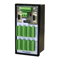
The GV 470 is a universal 8-channel splitter designed to distribute impulse signals from an incremental encoder or measuring system to up to eight target units. This device is built into a compact, space-saving housing suitable for mounting on DIN rails, making it a versatile component for industrial automation systems.
The primary function of the GV 470 is to take an input signal from an incremental encoder and replicate it across multiple output channels. This allows a single encoder to drive several different devices or systems simultaneously without signal degradation. The device is highly adaptable, supporting both standard RS422 signals and HTL (24 V) signals. It can handle both differential (symmetric) and single-ended (asymmetric) characteristics, providing flexibility for various encoder types.
A key feature of the GV 470 is its ability to provide potential separation between the input and output signals. This isolation helps to protect connected equipment from electrical interference and ensures signal integrity. For applications where potential separation is required, the input encoder must be supplied from a remote power source. However, the device also offers the option to connect its internal 5.3-volt power supply to the "0" and "+5" terminals for auxiliary encoder supply, though this will disable potential separation and tie the encoder potential to the general ground.
The GV 470 includes separate cascading inputs and outputs, which enable the creation of larger systems with multiple units. This cascading capability allows for a total of n x 8 output channels without sacrificing any regular output terminals. Beyond simply expanding the number of outputs, cascaded configurations also support remote selection and switching between several input encoders, adding a layer of control and flexibility to complex setups. This means that during operation, it is possible to switch over from one source encoder to another at any time, effectively allowing cascaded units to function as a cross-switch.
The device offers a user-friendly interface for configuration and monitoring. The input signal to be distributed is connected to an 8-position input terminal. The appropriate input level (RS422 or HTL 10-30 V) is selected using DIL switches, which allow for individual setting of each input terminal. This granular control ensures compatibility with a wide range of encoders. For RS422 settings, or HTL settings with impulse levels below 15 volts, both non-inverted and inverted input signals (differential input) are required. For HTL levels above 15 volts, users have the option to either use the inverted inputs or leave them unconnected, as the unit supports both differential and single-ended operation with higher input levels. The DIL switch settings for input lines A, /A, B, /B, Z, and /Z should be set in pairs (e.g., 1 with 2, 3 with 4, 5 with 6) for optimal performance.
Each of the eight output channels provides push-pull characteristics with individually adjustable output levels. This means that each output can be configured to deliver signals at a specific voltage, ranging from 5.5 to 30 volts, allowing for tailored integration with different target units. When the "Level" terminal on an output strip is left unconnected, the output level defaults to approximately 5 volts. Applying a remote DC voltage higher than 5.5 volts to this terminal will determine the output swing of the impulses. All common GND lines of the outputs are interconnected and also linked to the minus pole of the unit's power supply. All output connectors share the same codification, making them interchangeable.
The device features LEDs for visual feedback on its operational status. A green LED indicates that power is supplied to the unit. Additionally, lower LEDs (yellow, red, orange) display the actual logical states of the input channels A, B, and Z. This allows for easy visual checking of input pulses, phase displacement A/B, and index pulse function, especially useful for very low input frequencies.
Cascading multiple units is straightforward. Pins 1, 3, 5, and 7 of the cascading output on one unit are connected to the corresponding pins of the cascading input on the next unit using a ribbon cable (motrona part # FK470). This method ensures that regular output terminals are not lost during expansion. In a cascaded setup, the "Select" input terminal on the 3-position power connector determines which encoder is active. A LOW (or open) signal on this input means the outputs refer to the encoder input of the same unit, while a HIGH (10-30 volts) signal means the outputs refer to the encoder input of the preceding unit. If only one common encoder is used, the select input of the first unit remains unconnected, and the select inputs of all subsequent units should be connected to the +pole of the power supply next to the select input.
The GV 470 is designed for reliable operation in industrial environments. The unit's internal components are protected, and its robust construction ensures longevity. The clear labeling of terminals and the use of LEDs for status indication simplify troubleshooting and maintenance tasks. The DIL switches, while used for initial setup, are protected within the unit, preventing accidental changes to critical settings.
The manual emphasizes the importance of proper installation, wiring, environmental conditions, cable screening, and earthing, all in accordance with general industrial automation standards. This proactive approach to installation helps to minimize potential issues and extend the device's operational life. The unit's design also considers safety, with warnings about potential damage or injury if instructions are not followed. Regular checks of the input and output signals via the LEDs can help identify any anomalies early, allowing for timely intervention. The modular nature of the device, with its cascading capabilities, also means that individual units can be replaced or serviced without necessarily disrupting the entire system, contributing to easier maintenance.
| power supply voltage | 10 – 30 Vdc |
|---|---|
| power consumption | approx. 100 mA |
| maximum frequency RS422 | 500 kHz |
| operating temperature range | 0 – 50 °C (32 - 113 °F) |
|---|---|
| storage temperature range | -25 - +75° (-13 - 158 °F) |
| mounting | Standard DIN rail |
| weight | approx. 400 g |
|---|---|
| dimension 1 | 72 mm (2.835’’) |
| dimension 2 | 60.5 mm (2.382’’) |