MC70001c_de.doc / Nov-15 Page 5 / 14
BAA
Z ZB
12345
6789
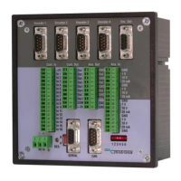
Encoder OUT
GND
SUB-D-9
SUB-D-9
(female on unit site)
(Buchse am Gerät)
33R
OUT
33R
OUT
Line driver
3.4 Steuer-Eingänge
Die 16 verfügbaren Steuereingänge sind auf der
Anschlussplatte mit In1 bis In16 beschriftet. Zur
leichteren Ansteuerung der Eingänge ist auf
derselben Steckerleiste nochmals die +24V-
Spannung herausgeführt.
Alle Eingänge sind PNP (nach +) schaltend und
beziehen sich auf dasselbe Potential wie die
Versorgungsspannung. Die Beschaltung ist aus
dem nachfolgenden Bild ersichtlich. Aufgrund
der Filterung ist eine minimale Signaldauer von
1 msec vorgegeben.
There are 16 general purpose control inputs,
marked with In1 to In16 on the front plate. For
easier wiring, also a +24V output terminal is
available on the same connector.
All inputs are of PNP type (switch to +) and refer
to the same GND potential as the power supply
voltage. The input circuit is shown in the
following drawing.
The minimum signal duration on the control
inputs is 1 msec due to input filtering.
+24V out
1 2 3 4 5 6 7 8 9 10 11 12 13 14 15 16 17
Steuereingänge, Klemmleiste “Cont. IN”
Control inputs, terminal strip “Cont. IN”
In 1
In 2
In 3
In 4
In 5
In 6
In 7
In 8
In 9
In 10
In 11
In 12
In 13
In 14
In 15
In 16
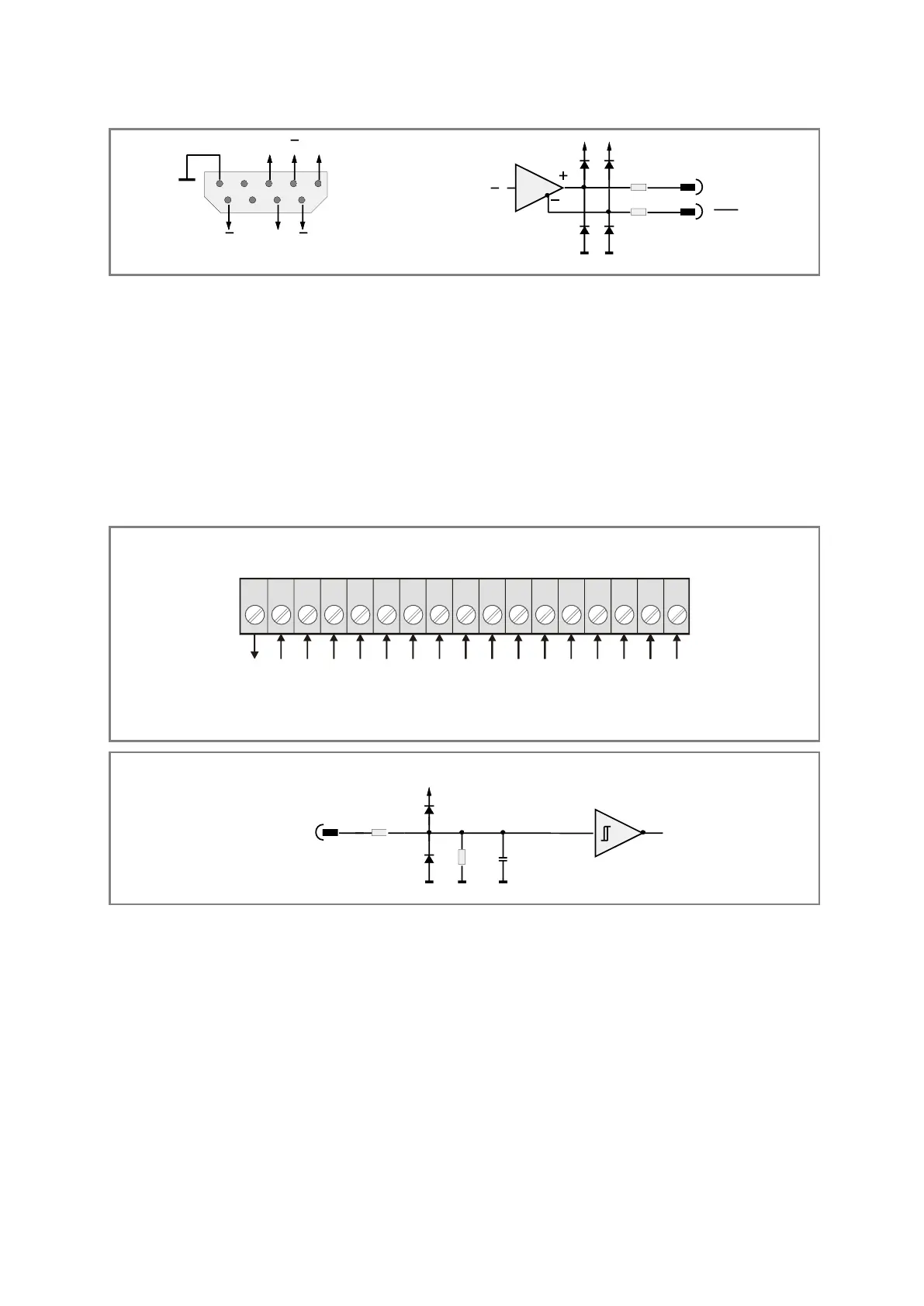
In
Control IN 1 - Control IN 16
10k
2k7 100nF
Low = 0 ... 5 V
High = 12 ... 35 V
3.5 Steuer-Ausgänge
Die 8 verfügbaren Steuerausgänge sind mit
Out1 bis Out8 beschriftet. Es handelt sich um
optisch isolierte Transistorausgänge mit PNP-
Schaltverhalten (gegen + schaltend). Die zu
schaltende Spannung muss an der Klemme
„Com+“ zugeführt werden. Wenn direkt die +24V
der Geräteversorgung geschaltet werden soll,
kann eine Brücke zwischen den Klemmen
„Com+“ und „+24V“ des Ausgangssteckers
eingelegt werden.
There are 8 general purpose control outputs
marked Out1 to Out8. These are opto-isolated
transistor outputs with PNP characteristics
(switching to +)
The switching voltage must be applied to
terminal “Com+”. Where you like to switch
directly the +24 volts of the power supply, you
can put a jumper from terminal “Com+” to
terminal “+24V” of the control output connector.
 Loading...