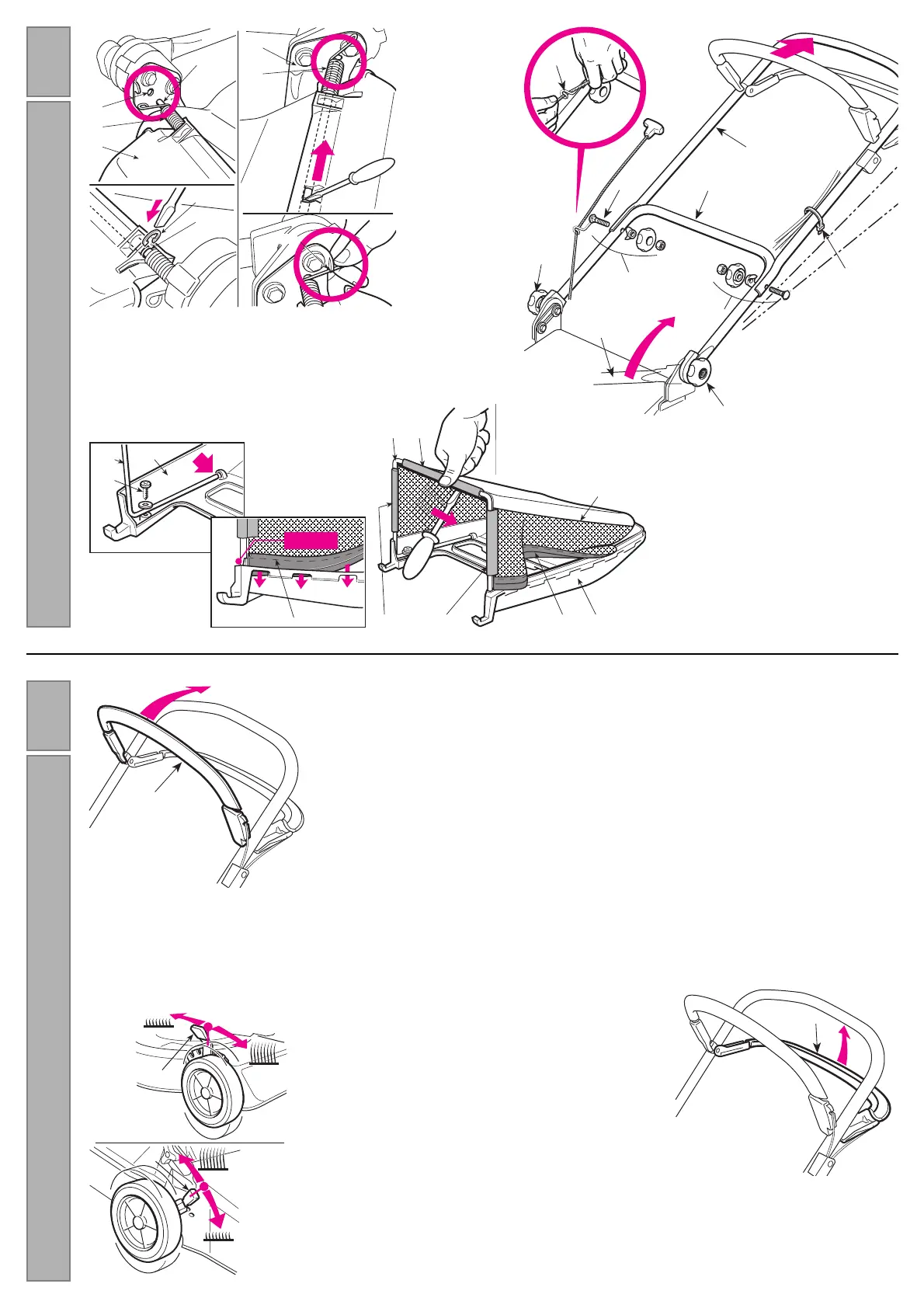
With the plastic part (11) upside-down, fas-
ten the frame (12) to the plastic part using
the screws (13).
Insert the frame (12) into the sack (14) and
attach the plastic profile (15) with the help of
a screwdriver, as shown in the drawing.
Fit the edge of the cloth (16) right into the
groove of the plastic part (11), starting 5-7
mm from the ends.
To fit the stone-
guard (1), the left
end of the pin (2)
must be pushed
through and then
inserted in the
hole of the left
support (3) in the
chassis.
Line up the other end of the pin with the relative hole in the right-hand support
(4) and, using a screwdriver, push the pin into the hole so that the groove (5)
can be reached. Insert the snap ring (6) into the groove and hook on the right
(7) and left (8) sprigs, as shown.
Return the lower part of
the pre-fitted handle (1) to
the work position and lock
into place using the lower
knobs (2).
Attach the upper part (3)
using the supplied screws
(4), ensuring that the spiral (5) of the starter cable is in the correct posi-
tion. Attach the control cables using the clips (6).
By loosening the knobs (2) the handle can be set at three different
heights.
The cutting height is adjusted using the levers (1).
The four wheels must be at the same height.
MAKE THIS ADJUSTMENT ONLY WHEN THE BLADE IS
STOPPED.
The blade brake is controlled by the
lever (1), and should be drawn up
against the handle when starting
and using the lawnmower. The
engine stops when the lever is
released.