6
ENGLISH
EN
3 ASSEMBLY
To avoid injuries and damage to prop-
erty, do not use the machine until all the
measures in these instructions have
been carried out.
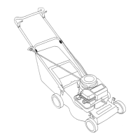
3.1 Wheels
Install the four wheels on the wheel axles in accor-
dance with fig. 1. Use the components below:
• Wheel 1:C.
• Locking washer 1:B.
• Wheel cap 1:A.
Install the rear wheel axle on the underside of the
machine in accordance with fig. 2. The angled
ends of the axle must fit into the slots in the side of
the machine. Use the components below:
• 2 locking loops 2:E (the smaller size).
• 4 screws with washers 2:F.
Install the front wheel axle on the underside of the
machine in accordance with fig. 2. The axle’s
height adjustment lever must fit into its locking de-
vice on the right side of the machine. Use the com-
ponents below:
• 2 locking loops 2:G (the larger size).
• 4 screws with washers 2:F.
3.2 Handle
3.2.1 The handle’s lower section
1. Install the cable holder 3:K on the handle’s low-
er section.
2. Press the handle’s lower section down into the
machine.
3. Lock the handle into position with the two
screws 3:L.
3.2.2 The handle’s upper section
Install the handle’s upper section into its lower sec-
tion in accordance with fig. 3. Use the two screws
3:I and the wing nuts 3:J.
Install the cable clamp 3:R on the right screw and
at the inside of the handle.
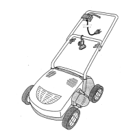
3.3 Start control
Install the start control on the handle’s upper sec-
tion in accordance with fig. 3. Use the two screws
3:H.
Secure the cable between the start control and the
motor with the two clamps 3:M and insert the cable
into the clamp 3:R.
Finally, fit the connection cable into the cable
clamp 3:K.
3.4 Collector
3.4.1 Assembly
See fig. 9 and 10.
1. Assemble the frame parts (9:X) and tighten the
two screws (9:Y).
2. Fit the collector to the frame part (10:Z).
3.4.2 Mounting to the machine
If the collector is installed in the wrong
way, there is a risk that it will interfere
with the rotating tool. Risk of damages
to the tool and collector.
Install the collector as follows:
1. Open the hatch according to fig. 4.
Note! The hatch 4:S shall not be completely
opened, only as shown in fig. 4. If the hatch is
fully opened, the collector attachment holes
will be blocked.
2. Insert the collector 4:T with its upper part
horisontal and locate the collector’s hooks into
the slots in the machine. Se fig. 5.
When the collector is fitted, its lower part shall
rest against the beam 5:U.
When the collector is fitted, its upper part shall
be competely horisontal. See fig. 6.
4 DESCRIPTION
4.1 Controls
4.1.1 Electric socket and relieving loop
The machine must be connected via an
earth leakage circuit breaker with fault
current 30 mA. There is otherwise a
risk of fatal electric shocks.
The connectioncable must be secured in the reliev-
ing loop (3:K) before it leaves the machine.
The cable must then be connected to 230 VAC
mains. If necessary, use an extension cord.
See “1.3”.
4.1.2 Start and stop control
Start
:
1. Tilt the machine until the front wheels rise
about 5 cm from the ground.
2. Press in and hold the button (3:P)
3. Squeeze the handle (3:O).
4. Release the button (3:P).
5. Let the front wheels down.
Stop
:
1. Release the handle (3:O).