Do you have a question about the Movacolor MC-BALANCE and is the answer not in the manual?
Defines symbols and key terms used in the manual.
General safety precautions, certifications, and operating environment limits.
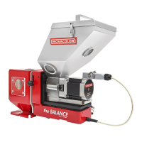
Lists and illustrates the main components of the MC-Balance unit.
Describes the weighing frame and the motor/dosing system.
Explains the function of the standard neckpiece and additive metering.
Compares different dosing systems, capacities, and materials.
Details motor types and material categories for dosing.
Covers unit handling, inspection, and physical mounting.
Details the procedure for switching between dosing systems.
Describes controller connections and available optional components.
Diagram showing electronic boards and their connections.
Explains how to navigate the interface and use the controls.
Describes the initial startup sequence and user access levels.
Explains how to lock and unlock the keyboard.
Details essential settings for initial setup.
Explains gravimetric/RPM modes and input signal types.
Describes automatic speed adjustment using tacho signals.
Settings for hopper fill level detection and alarms.
Configuration of deviation alarms and master reset functions.
Configuration of user levels, network, and unit properties.
Steps for calibrating the loadcell and verifying its accuracy.
Explains the benefits and methods of material pre-calibration.
Guides on making, selecting, and managing material calibrations.
Basic production control and testing procedures.
Details for gravimetric and RPM modes in injection molding.
Details for gravimetric and RPM modes in extrusion.
Explains switching control modes and saving production data.
Creating, selecting, and deleting production jobs.
Overview of manual and automatic filling methods.
Details on using the support frame for external loaders.
Configuration for ME and MV hopper loaders.
Tips for efficient hopper filling.
How to monitor material usage.
General behavior, history, and configuration of alarms.
Detailed explanations of specific error codes.
Searching, renaming, and deleting files (jobs, curves).
How events and alarms are logged and managed.
Key variables affecting performance and reset conditions.
Troubleshooting for common issues like deviations, slowness, and signal problems.
Detailed diagrams for mainboard, inputs, outputs, and signals.
Overview of control functions, communication interfaces, and technical data.
Drawings showing the physical size with the standard neckpiece.
Drawings showing the physical size with the ME25G hopper.
Drawings showing the physical size with the MV25G hopper.
Drawings showing the physical size with the support frame.
| Type | Gravimetric Batch Blender |
|---|---|
| Operating Temperature | 0°C to 40°C |
| Storage Temperature | -20°C to 60°C |
| Connectivity | Ethernet, USB |
| Accuracy | +/- 0.1% |
| Display | Touchscreen |
| Power Supply | 50/60 Hz |
| Dimensions | Varies depending on model |
| Weight | Varies depending on model |