– 1 – – 2 – – 3 –
P/N: 1802024060030
V2406A Series
Quick Installation Guide
First Edition, November 2014
Overview
The V2406A-C2 uses the Intel® Celeron® 1047UE processor and
the V2406A-C7 uses the Intel® Core™ i7-3517UE processor. Both
models feature 4 RS-232/422/485 serial ports, dual 10/100/1000
Mbps LAN ports, 3 USB 2.0 hosts, and 2 CFast sockets. The
computers provide 2 DVI-I outputs, making them particularly
well-suited for industrial applications such as rolling stock, SCADA,
and automation systems.
Package Checklist
Before installing your V2406A computer, verify that the package
contains the following items:
• V2406A series embedded computer
• Wall mounting kit
• Documentation and software CD or DVD
• Quick installation guide (printed)
• Warranty card
NOTE: Please notify your sales representative if any of the above
items are missing or damaged.
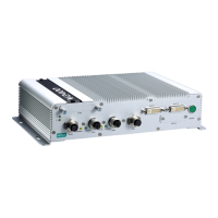
V2406A Panel Layout
V2406A Front View
V2406A Rear View
LED Indicators
The following table describes the LED indicators located on the
front and rear panels of the V2406A.
Power is on and functioning normally.
Power is off or power error exists.
Storage Yellow CFast card, HDD, or
CFast card, HDD, or SSD is not
transmitting data
Serial port is transmitting data
Serial port is not transmitting data
Serial port is receiving data
Serial port is not receiving data
Installing the V2406A
The V2406A can be DIN-rail mounted, wall mounted, or VESA
mounted. Some mounting kits may need to be purchased
separately. Refer to the V2406A Hardware User’s Manual for
detailed installation instructions.
Connector Description
Power Connector
Connect the 12 to 48 VDC LPS or Class 2 power line to the V2406A
M12 A-coded power connector. If the power is supplied properly,
the Power LED will light up. The OS is ready when the Ready LED
glows a solid green.
he branch circuit overcurrent protection must be rated
Grounding the V2406A
Grounding and wire routing help limit the effects of noise due to
electromagnetic interference (EMI). Run the ground connection
from the ground screw to the grounding surface prior to connecting
the power. Note that these products are intended to be mounted to
a well-grounded mounting surface, such as a metal panel.
This product is intended to be mounted to a well
grounded
mounting surface, such as a metal panel.
SG: The Shielded Ground (sometimes
called Protected Ground) contact is the
central pin of the power input
connector
. Connect the SG wire to an
appropriate grounded metal surface.
DVI-I Outputs
The V2406A comes with 2 DVI-I female connectors for the DVI
display. These output interfaces are all located on the front panel
of the product. Be sure to use the correct cable to connect the
computer to the display.
CFast Slot
The V2406A has 2 CFast sockets. One slot is located on the front
panel for storage expansion and another slot is located inside the
case for OS storage. Both slots support CFast Type-I/II with DMA
mode. To install a CFast card, remove the outer cover or the
bottom panel, and then insert the CFast card in the socket. When
finished, push the cover into the socket or put the bottom case
back and refasten the screws.
USB Hosts
The V2406A has one USB port with an M12 D-coded connector on
the front panel, and two USB ports with type A connectors on the
rear panel. These USB ports can be used to connect flash disks for
storing large amounts of data.